The modern Lada Granta model is in demand among domestic car enthusiasts due to its optimal cost and sufficient reliability. Good strength and low cost of consumables further stimulate demand among the population. The downside of the car is frequent breakdowns in the electrical part. On-board systems often fail. The website contains a detailed electrical diagram of Grant with explanations and interpretation.
Full pinout of Grant, divided into several sections for a more detailed image and easier perception. Present here.
- The engine compartment - the harness combines all the elements of the wires located in the area of the engine and main instruments.
- Salon module. The design is further divided into zones that provide for the connection of individual parts of the wiring.
- Instrument panel module. All elements coming from sensors, instruments and indicators are concentrated here.
- The rear harness is located in the rear of the car and is responsible for supplying power to the lighting, lock and instrument modules.
All the given transcripts are taken from the manufacturer’s official instructions and fully comply with the factory designations and the standard version diagram.
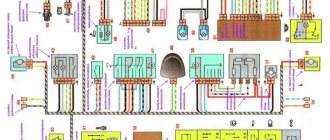
Grant's electrical circuit responsible for the engine compartment
Here are the main parts of the Lada Granta wiring, which are responsible for the normal operation of the power plant:
- 1 – power supply to the headlight, front right;
- 2 – power supply for windshield washers;
- 3 – voltage to the left side of the head optics;
- 5 – on-board power supply;
- 6 – head fuse block;
- 7 – generator;
- 8 – horn;
- 9-11 – terminal blocks to the dashboard;
- 12 – contact pair of rear headlights;
- 13 – main radiator fan drive.
Lada Granta diagram - ignition part
- 1 – indicator of lubricant pressure in the crankcase of the power plant;
- 2 – generator connector;
- 3 – power supply to the fuel mixture supply valve;
- 4 – cooling system thermometer;
- 5 – sending a signal to the dashboard;
- 6 – adsorber purge;
- 7 – speedometer;
- 8 – mass air flow sensor;
- 9 – DPKV;
- 10 – DC in front of the catalyst;
- 11 – control pulse device;
- 12 – oxygen concentration sensor in exhaust gases;
- 13/14 – coil and spark plugs, respectively;
- 15 – injector drivers;
- 16 – ignition contact group;
- 17 – detonation measurement sensor.
Grant instrument pinout - dashboard diagram
This part is the most difficult. The large number of pins and the miniature size of the terminals greatly complicates the search for the required group:
- 1/2 – connecting blocks for the front electrical harness;
- 3/4 – similar for the feed harness;
- 5 – lighting control unit;
- 6 – ignition switch module;
- 7 – on-board computer;
- 8 – lever for switching the position of the wipers;
- 9 – tidy;
- 10 – control of emergency modes;
- 11 – cargo compartment lid lock;
- 12 – diagnostic connector;
- 13 – block for the air intake drive;
- 14 – button to turn off the heated rear windshield;
- 15 – emergency contact;
- 16 – brake light switch;
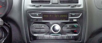
- 17/18 – contact group – output to radio equipment (radio tape recorder);
- 19 – rotating equipment module;
- 20/41 – driver/passenger airbag drive;
- 21 – horn power supply;
- 22 – mounting block group;
- 24 – cigarette lighter group;
- 25 – backlight for stove control;
- 26 – interior lamp;
- 27 – contact group of the ignition switch;
- 28 – controller;
- 29 – incoming connector to the rear of the on-board network;
- 30 – electronic part of the gas pedal;
- 31 – additional resistor;
- 32 – stove motor;
- 33 – heater switch block;
- 34 – door lock module;
- 35/36 – cooling system head fan relay;
- 37 – compressor relay wiring;
- 38 – additional relay or reverse indication coil;
- 39 – air conditioner switch button;
- 40 – automatic transmission drive;
- 42 – evaporator thermometer;
- 43 – output to the rear wiring harness.
How to connect an emergency button
The turn signal breaker circuit for the VAZ 2101 and their modifications is as follows:
As a connection diagram, we use a diagram from a VAZ 2106 with a six-pin button for turning on the alarm. We'll change this diagram a bit, the overall look will remain the same, but we'll use different anchor points. (This is done to simplify installation and does not affect performance in any way) This diagram looks like this:
Work order:
You can also use an old relay by connecting it as in diagram 2106, but the original relay 2101 uses outdated technology and is very sensitive to load changes, so the process of replacing the relay is described below. We remove the old turn signal relay by unscrewing the nut securing it to the front panel and disconnecting the three wires from it. (the colors of the wires must correspond to the colors in diagram 2101) In order not to lose the nut, immediately put a new relay in this place and lightly screw the nut on. (don’t delay) I hope that you have already decided on where you will install the hazard warning button... If not, then decide quickly, because we are starting to lay wires and pull them to where the hazard warning button will be. My button is located in the console for the VAZ 2107 receiver in place of the potentiometer, but as an option, I was thinking of installing the button in the radio plug in the dashboard. (to the right of the steering wheel)
Relay: Relay contact 2 is connected to the wire removed from contact “L” of the old relay and to contact 7 of the hazard warning button. Relay contact 1 is connected to contact 4 of the hazard warning button. Relay contact 3 is connected to the wire removed from contact “P” of the old relay. We attach the wire from contact 4 to ground (vehicle body). The optimal place is under the relay mounting nut. By the way, after all of the above has already been done, you can tighten the relay mounting nut. (don’t overdo it, the mount is plastic, it can break)
Button: Button pin 4 should already be connected to relay pin 1. Contact button 2 is connected to the wire removed from the “+” contact of the old relay. Button contact 7 should already be connected to relay contact 2. We connect button contacts 1 and 3 to the steering column turn signal switch; the connection order is not important. The locations in the block look like this (there are 8 contacts in the block we need):
Contact button 8 is connected to the positive, which does not depend on the position of the key in the ignition switch. You can use the plus from the cigarette lighter. If the plus is taken from the battery or from the generator, then it is advisable to protect this circuit with an 8A fuse.
That's the whole installation. After this, we tighten the resulting braid of wires with clamps and secure the wires so that they do not dangle or fray. You can attach new conductors with electrical tape to existing braids. We reinstall the instrument panel, restore the connections of the heater switches, dimensions and lighting of the instrument cluster. Now you have an alarm, use it and enjoy it... Thanks for the article, RavenDark. vaz2101.spb.ru
Addition In general, here is the most normal emergency scheme for a penny
note: it is better to use relay 05, not 06 as in the diagram. With 05 relays, the lamp on the dash blinks in time with the turn signals and you can control how many times the “thank you” blinks in traffic. and 06 flashes along with the hazard warning button.
| : sever | 17 2021 07:07 | : 10/22/2012 | |
| :parfent | 22 2021 11:34 | : 1.06.2013 | |
Grant ECU pinout
The Lada Granta uses two types of electronic engine control units. Fundamentally, the systems differ slightly, which excludes the possibility of their interchangeability.
| Contact | 11183-1411020-51/52 | 11186-1411020-21/22 |
| A1 | DPKV | |
| A2 | Not involved | |
| A3 | Entering the first knock sensor | |
| A4 | Not used | |
| IN 1 | DPKV | |
| AT 2 | Not involved | |
| AT 3 | Input of the second knock sensor | |
| AT 4 | Main relay output | Not used |
| C1 | Empty | |
| C2 | DTV | |
| C3 | Mass air flow sensor | |
| C4 | UDC | |
| D1 | DDC weight | |
| D2 | Empty | |
| D3 | DTOZH | |
| D4 | Not applicable | |
| E1 | Zeroing the TPS | |
| E2 | Empty | CAN L |
| E3 | Empty | CAN H |
| E4 | Canister purge valve output | |
| F1 | Body from DTV | |
| F2 | Speedometer input | |
| F3 | Not applicable | DFM |
| F4/G4/H4/J4 | Output from injector No. 1/2/3/4 | |
| G1 | Antifreeze temperature sensor ground | |
| G2/G3 | Not used | |
| H1 | On-board electronics grounding | |
| H2 | UDC | |
| H3 | Not involved | Battery charge indicator output |
| J1 | Terminal No. 15 from the ignition switch | empty |
| J2 | Entrance No. 2 TPS | |
| J3 | DDC | |
| K1 | Supplying voltage to the TPS | |
| K2 | Entrance No. 1 TPS | |
| K3 | UDC | |
| K4 | DDK heater power connector | |
| L1/M1 | Leads to the ignition coil ¼ and 2/3 cylinders respectively | |
| L2/M2; L3/M3 | Not involved | |
| L4/M4 | Throttle actuator pin 5/6 | |
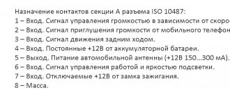
Car alarm connection points for Lada Granta 2021, automatic transmission, Starline A93 2can2lin
Ignition switch: +12 – brown ign 1 – blue/black acc – pink starter – connect to the gray connector at the bottom of the fuse box, the outermost red
From the can doors , brake pedal , engine running . When activating the comfort function, be sure to allow control of the standard security system.
Instrument panel: turns – blue and blue/black c an h – pink/green c an l – yellow/blue
LIN bus - red/green to the gap (white/green towards the connector, white towards the car) in the harness from the driver's door
trunk - black/blue from the trunk, diode in the gap hood - standard limit switch white/black, diode in the gap
The keyless bypass was trained not when the ignition was turned on, but rather when it was attempted to start (before starting, both learning methods gave an error). The engine had a mass air flow sensor.
Passage under the hood through the plastic plug of the clutch pedal.
Grant relay diagram
Relay location in the main mounting block located in the engine compartment:
- 1 – drive of the cooler of the cooling system;
- 2 – central locking protection;
- 3 – secondary starter relay;
- 4 – additional part of the relay;
- 5 – turn signal and emergency signal breaker relay;
- 6 – wiper drive protection;
- 7/9 – insertion of high/low headlight modes;
- 8 – horn protection element;
- 10 – heated aft windshield;
- 11 – main relay block;
- 12 – fuel pump relay.
Detailed diagram of the VAZ Grant (dashboard)
The vehicle is supplied to the market with a 32-pin instrument panel as standard. The standard pinout of the Grant shield has only 26 pins involved. Residual connectors are provided for the possibility of adding equipment or custom modifications:
- 1 – to the low oil pressure sensor in the engine crankcase;
- 2 – to the handbrake indication switch;
- 3 – intended for service needs when diagnosing the instrument panel;
- 4 – to external lighting switches;
- 5/6 – similar for right and left turn signals, respectively;
- 7/8 – CAN L/H;
- 9 – indication of seat belt position;
- 10 – contact of the Reset button of the steering column lever;
- 11 – response of the brake fluid reservoir sensor;
- 12/13 – on the head optics, high/low beam position;
- 14/15 – foglight terminals front/rear, respectively;
- 16/18 – receiving immobilizer antenna signal;
- 17 – ground wire of the instrument panel;
- 19/21 – to terminal No. 30/15;
- 20 – for the drive of the electric power steering unit;
- 22 – for door closing sensors;
- 23/24 – MK buttons for forward and reverse, respectively;
- 25 – for an environmental thermometer;
- 26 – gas tank float indication.
Lada 2101 Cat Basilio › Logbook › Installing an alarm system
I decided to put the emergency lights on my baby because I feel bad that they are missing out on food or giving in to food, and I can’t even thank you!
Installation of alarm systems on VAZ 2101 and their modifications.
I think that many people have had the desire to equip their car with an alarm system. After all, if anyone doesn’t know, the emergency warning system began to be installed on cars of the VAZ family starting with model 2103. But you must admit that sometimes you want to flash the emergency lights to the person who let you pass in a traffic jam, wink at a pretty girl, or simply, almost legally, stop at public transport stop in front of the trolleybus and run to the stall almost without violating traffic rules...
So, for those who are interested in all of the above...
First, I’ll tell you what materials and tools we will need to do this work.
1. Key 10. 2. Phillips screwdriver. 3. Wire cutters. 4. Pliers. 5. Flat screwdrivers. 6. Knife. 7. A lot of patience, because you will remember more than once a certain MOTHER and VAZ designers...
1. Electrical tape or heat shrink tubing. 2. Installation wire (about 5 meters). Preferably pieces of different colors. 3. Turn signal and hazard warning relay from VAZ 2106. (four contacts) 4. Hazard warning button. (six contacts) 5. Relay connector. 6. Connector for connecting a button.
Operating time: 2-3 hours at best
Work order:
You can also use an old relay by connecting it as in diagram 2106, but the original relay 2101 uses outdated technology and is very sensitive to load changes, so the process of replacing the relay is described below.
We remove the old turn signal relay by unscrewing the nut securing it to the front panel and disconnecting the three wires from it. (the colors of the wires must correspond to the colors in diagram 2101) In order not to lose the nut, immediately put a new relay in this place and lightly screw the nut on. (don't delay)
I hope that you have already decided where you will install the hazard warning button... If not, then decide quickly, because we are starting to lay the wires and pull them to where the hazard warning button will be. My button is located in the console for the VAZ 2107 receiver in place of the potentiometer, but as an option, I was thinking of installing the button in the radio plug in the dashboard. (to the right of the steering wheel)
Relay contact 2 is connected to the wire removed from contact “L” of the old relay and to contact 7 of the hazard warning button. Relay contact 1 is connected to contact 4 of the hazard warning button. Relay contact 3 is connected to the wire removed from contact “P” of the old relay. We attach the wire from contact 4 to ground (vehicle body). The optimal place is under the relay mounting nut.
By the way, after all of the above has already been done, you can tighten the relay mounting nut. (don’t overdo it, the mount is plastic, it can break)
Button contact 4 should already be connected to relay contact 1. Contact button 2 is connected to the wire removed from the “+” contact of the old relay. Button contact 7 should already be connected to relay contact 2. We connect button contacts 1 and 3 to the steering column turn signal switch; the connection order is not important.
Contact button 8 is connected to the positive, which does not depend on the position of the key in the ignition switch. You can use the plus from the cigarette lighter. If the plus is taken from the battery or from the generator, then it is advisable to protect this circuit with an 8A fuse.
After this, we tighten the resulting braid of wires with clamps and secure the wires so that they do not dangle or fray. You can attach new conductors with electrical tape to existing braids.
We reinstall the instrument panel, restore the connections of the heater switches, dimensions and lighting of the instrument cluster.
Now you have an alarm system, use it and enjoy...
source
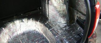
Lada Granta: wiring diagram for rear wiring harness devices
The rear part of the car wiring is responsible for the equipment of the stern and sides of the car. all additional equipment is connected exclusively through this part of the highways:
- 1/2 – contact group for the dashboard;
- 3/4 – direction indicators;
- 5 – handbrake indicator;
- 6 – rear window heating contact;
- 7 – interior lamp;
- 8 – indicator of the driver’s seat belt position;
- 9 – cargo compartment illumination lamp;
- 10 – fuel pump drive;
- 11/15 – aft dimensions for the left and right sides;
- 12 – trunk lid lock drive;
- 13 – button for turning on the interior lamp;
- 14 – additional stop chain;
- 16-19 – door terminal blocks for the rear left, rear right, front left and front right doors;
- 20 – airbag control drive;
- 21 – contact group of license plate lights;
- 22 – on the dashboard;
- 23/24 – rear speed indicator sensors;
- 25/26 – seat belt pretensioners;
- 27 – group of dashboard contacts.
Installing the ignition switch
A new lock on Granta can be purchased at a price of 1,800 rubles. This is the cost of the kit with all the door cylinders and trunk lid. Installation is carried out in reverse order. We first install it on the shaft and try on the casing so that the lock sits exactly in the hole. After which you can finally tighten the fastening bolts.
It is necessary to tighten until the head of the bolt comes off when a certain torque is reached.
After which you can install the casing in place, having previously connected all the power wires.
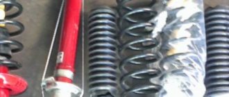
Preventive measures
In order for the factory wiring of the Lada Grant to serve for a long time and not break, experienced experts strongly recommend following a number of simple rules.
- Periodically check all contact connectors and terminals for oxidation and rust. Such damage to the connections can cause a short circuit and a critical decrease in the conductivity of the line, which is perceived by the on-board computer as an error or breakdown.
- Use only original consumables and electronic components. The use of counterfeit products does not guarantee the functionality of the circuit. At the same time, some elements, when damaged, cause a voltage drop in the network, which becomes a direct cause of failure of other equipment or a fire.
- Use special oil to treat contact groups. The fluid is sold in auto shops or electronics stores. After treatment, the contacts are covered with a moisture-impermeable layer, which increases their service life by 2-3 times.
- Carefully monitor the charge level and condition of the battery. The wiring of the Lada Granta critically perceives a significant voltage drop in the on-board circuits. As a result, this may cause damage to the firmware of electronic control units.