How does the intake manifold length change system work?
An intake manifold with a variable length system is used in both gasoline and diesel engines to ensure better filling of the combustion chamber with air at different engine speeds.
At low speeds, maximum torque is required to be achieved as quickly as possible, which is achieved by using a long intake manifold. High revs bring the engine to maximum power with a short intake manifold.
This system works the same on most cars. An axis with flaps is installed in the intake manifold, which block or open the path to air flow along one of two paths - short or long.
The system for changing the length of the intake manifold usually consists of the following elements:
- receiver with check valve
- solenoid valve
- mechanism for changing length (pneumatic chamber)
- axle with flaps
- connecting vacuum tubes
- wiring to the solenoid valve
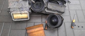
Let's look at the design and operation of the system in more detail using the example of a Chevrolet Lacetti.
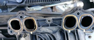
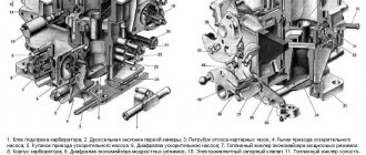
In the photo below I noted:
- red arrow – receiver with check valve
- green arrow – solenoid valve
- blue arrow – wiring to the solenoid valve
- yellow arrow – mechanism (pneumatic chamber) for changing length
- numbers - connecting vacuum tubes: 1 - from the solenoid valve to the mechanism (pneumatic chamber), 2 - from the manifold to the receiver, 3 - from the receiver to the valve.
With the engine turned off, the rod of the mechanism (pneumatic chamber) is fully extended and the system is in the state of a short manifold. As soon as we start the engine, a vacuum is created in the manifold and the pressure drops to 30-33 kPa. Voltage is applied to the valve and it opens, thereby releasing vacuum from the manifold through the receiver into the working mechanism (pneumatic chamber). The pneumatic chamber retracts its rod and, turning the valve axis, transfers the system to a long manifold, which ensures throttle response at low engine speeds. The system will remain in this position until the engine reaches a speed of 4.5 thousand rpm. After this, the ECU turns off the voltage supply to the valve and it closes, cutting off the vacuum supply to the pneumatic chamber. The pneumatic chamber rod should now fully extend and rotate the damper axis again into short manifold mode. But how will it come out if the pneumatic chamber is sealed and it needs air access so that the spring in the pneumatic chamber can move the rod? It's like putting a bottle in water upside down. Water will not get into it until you make a hole in the bottom to let the air out.
For these purposes, the solenoid valve also has a third fitting, which is closed by a cap (filter), which is located at the bottom and the green arrow points to it. This is an atmospheric fitting. When the voltage is turned off, the solenoid valve not only blocks the vacuum from the receiver to the pneumatic chamber, but also opens the transition from the pneumatic chamber to the atmospheric fitting, allowing the pneumatic chamber to draw in air and extend the rod.
Now let's briefly look at the device and check each node separately.
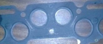
Manifold tuning
Engine tuning is a whole range of work to refine its individual components and parts. The intake manifold can also be modified to improve engine performance.
Tuning this part has two directions:
- to overcome the negative influence of its form;
- for finishing the internal surface.
What does form have to do with it?
The flow of air or working mixture in the manifold is uneven due to its shape. If the manifold is asymmetrical, then the largest amount of air or fuel-air mixture will enter the first cylinder, and less will enter each subsequent one. The symmetrical one also has a drawback: there, the largest amount of air enters the middle cylinders. In both cases, the cylinders operate unevenly on mixtures of different qualities. As a result, engine power decreases.
Tuning, in this case, involves replacing the standard intake manifold with a multi-throttle intake system. Its design is such that the air flows supplied to the cylinders are independent of each other, since each of the cylinders is equipped with its own throttle valve.
"Internal" work
If there is a lack of funds, tuning can be done more cheaply, almost for nothing. Inside the reservoirs there are almost always a large number of irregularities and tides, and the surface is rough. All together, this causes unnecessary turbulence that interferes with the quality filling of the cylinders. During measured driving, this phenomenon is almost unnoticeable, but if you want to achieve greater efficiency from the engine, you need to fight these shortcomings.
Tuning a standard intake manifold involves grinding its inner surface in order to remove tides and roughness. You need to grind not until a mirror appears, but only until the entire surface is uniform. If you overdo it, drops of fuel will condense on the walls and tuning will give a completely opposite result.
Finally, in order for the tuning to be as complete as possible, you need to pay attention to the interface between the manifold and the cylinder head. Often, a step remains in this place, interfering with the normal flow of air flow, which must be eliminated (this is where cylinder head tuning begins).
In the power supply system of any internal combustion engine, the intake manifold plays a serious role. It conveys the air or air-fuel mixture to the cylinder head, from where it enters the combustion chamber. The more, the greater the amount of air (mixture) passes through the intake manifold and the stronger its influence on engine parameters.
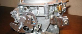
Intake manifold length control solenoid valve
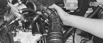
The valve consists of a body, a locking mechanism, three fittings and an electromagnetic coil. To remove the valve from the car, just bend the latch on the receiver side and slide the valve down
The valve has three fittings. One of them (atmospheric) is closed with a lid. It must be removed to check and remove dirt.
To check the valve's closing properties, simply blow into the side fitting. In this case, the air should go out into the lower (atmospheric) fitting, but not into the upper one. If you apply voltage to the valve, then everything should be the other way around.
To check the valve winding, just press the clamp of the wire block and remove it
There will be two contacts visible on the valve. You need to connect an ohmmeter to them and measure the resistance, which should be several ohms. If the resistance is normal and the valve does not work, then you need to check the incoming voltage at the block, which should be about 12 V. Don't forget to start the engine to measure the voltage.
How does the manifold affect engine performance?
When the engine operates at maximum speed with the gas pedal fully depressed, the speed of air in the manifold approaches (and in sports cars noticeably exceeds) the speed of sound. At such speeds, any turn and the slightest bump turn out to be a serious obstacle, which greatly increases the resistance of the collector to air flow. As a result, less air enters the cylinders, so engine power drops. In this mode, the carburetor often produces an over-lean mixture, the burning rate of which is tens of times faster than normal. Therefore, the air-fuel mixture explodes, which leads to damage to valves, pistons and other engine elements.
Equally important is a high-quality connection between the manifold and the carburetor or. If the sealing elements are worn out or the fastening nuts are poorly tightened, then air leaks occur at the contact point, resulting in an over-lean mixture and explosions in the combustion chamber.
Receiver (vacuum tank) of the system for changing the length of the intake manifold
This is a cylindrical container with a check valve inside. The check is very simple and consists of two points:
- check integrity to ensure there is no vacuum leak
- disconnect the tube going to the solenoid valve, and disconnect the second tube from the manifold (tube No. 2). Blow into this tube - no air should pass through. But when sucked into itself, the air must pass through!
Working mechanism (pneumatic chamber) of the system for changing the length of the intake manifold
This is the weakest link in this chain.
The pneumatic chamber consists of a body (metal or plastic), a rod, a diaphragm and a spring.
Most often, the system for changing the geometry of the intake manifold fails precisely because of a worn-out pneumatic chamber diaphragm. It can be called a consumable item.
To check the integrity of the spring and diaphragm, simply disconnect the vacuum tube and press in the rod. The rod should enter without jamming, and when released, it should move out sharply. This means the spring is intact and the damper axis does not jam.
Now press the rod in and close the fitting with your finger. The rod should not come out of the pneumatic chamber completely. If it comes out, it means the diaphragm is torn.
Here is a video of the working mechanism with a slightly worn diaphragm. Look closely
The diaphragm still works somehow. The rod retracts at idle, but as soon as you press the gas pedal a little, the rod comes out a little. This happens because when the throttle valve opens, the pressure in the manifold increases and the vacuum decreases. And this vacuum is no longer enough to hold the torn diaphragm. Although it would hold an entire diaphragm without problems.
Upon reaching a speed of 4.5 thousand rpm, the rod extends completely, as it should be. This means that the entire system is working properly, except for the diaphragm.
But the main problem is not even that the collector is now incorrectly converted to long/short. Or rather, this is also a big problem, but there is an even more serious one.
The fact is that up to 4.5 thousand rpm the solenoid valve is open and, naturally, releases a vacuum into the pneumatic chamber with a torn diaphragm, which leads to the suction of unaccounted air into the intake manifold! Because of this, the correct operation of the engine at low and medium speeds is disrupted. There are dips, jerking, an increase in idle speed and, accordingly, fuel consumption hits your pocket even more.
Therefore, the pneumatic chamber must be replaced.
If you notice that the diaphragm is damaged, and the house is still very far away and there is no opportunity to buy a new pneumatic chamber, then you can do the following:
- Disconnect the vacuum tube from the manifold and plug the fitting on the manifold. Attention!!! You just need to look for a plug that fits ON the fitting (for example, bend the hose and secure it with wire, the rubber part from a medical pipette, etc.), and NOT into the fitting (matches, toothpicks, etc.). This is exactly what is needed to prevent your plug from being sucked into the manifold! I used a piece of vacuum hose that was bent and crimped with wire.
- Recess the pneumatic chamber rod and secure it in this position with wire, a clamp or something similar.
So you can calmly drive wherever your eyes look. But remember that at high engine speeds the dynamics will be slightly worse.
The value of the length and shape of the intake manifold pipes
Recently, great importance has been attached to the length and shape of the intake manifold pipes or channels. Sharp curvatures and sharp corners are unacceptable in the channel design, since in these places fuel mixed with air will inevitably settle on the walls. Modern manifolds use a principle born in the depths of sports car workshops - all individual channels of all cylinders, regardless of the distance from the center, are of equal length. This design helps combat the so-called “Helmholtz resonance”. The flow of the fuel-air mixture at the moment the intake valve opens moves along the manifold channel towards the cylinder at a significant speed. When the valve closes, the air that has not had time to pass into the combustion chamber continues to press against the closed valve, creating an area of high pressure. Under its influence, the air tends to return back to the upper part of the collector. Thus, a counterflow is formed in the channel, which stops the moment the valve opens next time. The process of changing the flow direction in traditional reservoirs occurs constantly and at a speed close to supersonic. The fact is that in addition to the opening and closing of valves, the air tends to constantly change direction in accordance with the phenomenon of resonance, which was discovered by Hermann von Helmholtz, the author of classical works on acoustics. Naturally, when the air continuously “hangs back and forth”, power losses are inevitable. For the first time, manifolds optimized for Helmholtz resonance were used in Chrysler V10 engines, which were equipped with cars and pickups. The design was subsequently adopted by other manufacturers.