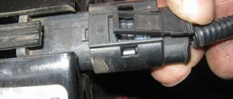
Measuring the voltage of battery and generator circuits with an avometer (tester, multimeter)
Note.
This article is universal and applicable to any make of car. Device capabilities in voltage measurement mode.
Checking battery voltage
The instrument scale is divided into color sections and allows you to evaluate the readings at a quick glance. Such a device already belongs to special-purpose equipment for personnel servicing batteries.
If, contrary to expectations, there is no increase in the on-board network voltage, you should begin troubleshooting either the generator itself or the devices that serve it. Under no circumstances should you test the performance of the generator “the old fashioned way.” We disconnected the battery and, if the engine did not stall, then the generator was working. I really sympathize with the diagnostician who will try to implement a similar technique on a modern injection (or, worse, diesel) car.
The winding resistance will decrease as the generator power increases. To check for the presence of an interturn short circuit (if there is noticeable mechanical damage on the winding or darkening of the wire insulation due to overheating), equipment from a specialized workshop is required.
It is more convenient to make this measurement with a digital meter with a fresh internal power supply. You can check more accurately if you have a stabilized voltage source. We return again to the use of an additional voltage source. Let's consider a method for checking generator components using this device and an avometer.
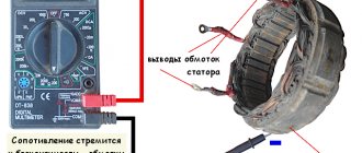
We move the switch and source regulator to the position corresponding to the lowest value (almost to “0”). To the “plus” terminal of the source we connect the red terminal of the avometer, which is turned on in the DC measurement mode. We connect the output of any of the windings to the black terminal of the avometer (see diagram 1).
We connect any of the terminals of the stator windings to the minus terminal of the source. In this case, we get a series connection of two windings. Using the regulator on the instrument panel, we set the voltage at which the avometer will show the maximum value of the measured direct current (in our case, 250 mA = 0.25 A). Then we measure the voltage obtained at the terminals of the reference source (measurement showed 1.25V). By carrying out such a measurement on all three pairs of windings, we will obtain fairly accurate voltage readings: the current is constant in all three cases (photo 6).
For a working generator (in the absence of interturn short circuit of the windings), these values should not differ by more than 5%. If the measurements give readings that differ by a larger value, this indicates an interturn short circuit in the winding, which reaches the maximum current value at a lower applied voltage. In this case, the generator does not produce sufficient voltage during operation at low engine speeds, and it also heats up noticeably.
Checking the operation of the generator voltage regulator relay
This value is 13.77 Volts, and if we take into account that the power to the rotor is not turned off, but only decreased, then we will be provided with 14 Volts. When all consumers are connected simultaneously, the voltage will be kept at least 13.77 Volts.
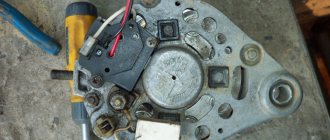
At the end of the work to check the functionality of the generator, you should make sure that the diodes of the rectifier bridge are in good condition (see Diagram 1). For this purpose, the Avometer has a switch position for testing semiconductor elements. Each of the diodes is tested for direct conductivity (photo 9)
and reverse directions (photo 10) of current flow.
Video
Source
Checking rectifier valves
A working valve allows current to flow in only one direction. Faulty - may not pass current at all (open circuit) or pass current in both directions (short circuit).
If one of the rectifier valves is damaged, the entire rectifier unit must be replaced.
A short circuit in the rectifier valves can be checked without removing the generator from the car by first disconnecting the wires from the battery and the generator. You can check with an ohmmeter, or using a lamp (25-40 W) and a battery, as shown in Fig. 7-8.
Rice. 7-8. Rectifier valve test diagrams:
I - checking simultaneously “positive” and “negative” valves; II - checking “negative” valves; III - checking “positive” valves; 1 — generator rotor; 2 - stator winding; 3 - rectifier valves; 4 - control lamp; 5 - battery
Note. In order to simplify the fastening of rectifier parts, three valves have a “plus” of rectified voltage on the housing. These are “positive” valves and they are pressed into one plate of the rectifier block. The other three “negative” valves have a “minus” of the rectified voltage on the housing and are pressed into another plate of the rectifier block.
First, check if there is a short circuit in the “positive” and “negative” valves at the same time. To do this, connect the “plus” of the battery through the lamp to terminal “30” of the generator, and the “minus” to the generator body (Fig. 7-8, I). If the lamp is on, then both the “negative” and “positive” valves have a short circuit.
The short circuit of the “negative” valves can be checked by connecting the “plus” of the battery through a lamp to the plug of the neutral wire of the stator winding, and the “minus” to the generator housing (Fig. 77-8, II)
The lamp burning means a short circuit in one or more “negative” valves.
It should be remembered that in this case, the burning of the lamp may be a consequence of the short circuit of the stator winding turns to the generator housing. However, such a malfunction is less common than valve short circuits.
To check for a short circuit in the “positive” valves, connect the “plus” of the battery through a lamp to terminal “30” of the generator, and the “minus” to the zero point output plug of the stator winding (Fig. 7-8, III). The lamp will indicate a short circuit in one or more “positive” valves.
A break in the valves without disassembling the generator can only be detected indirectly when checking the generator on a bench, by a significant decrease (by 20-30%) in the amount of current supplied compared to the rated one. If the generator windings are working properly and there is no short circuit in the valves, then the reason for the decrease in the output current is a break in the valves.
Diagnostics of malfunctions of the VAZ 21213, 21214 (Niva) generator
The battery discharge indicator light comes on when the engine is running.
The coolant pump belt is loose or broken
Tighten or replace the belt
The voltage regulator is damaged. To check, use two DC sources of 12 and 15 V (see Electrical Equipment) or replace the regulator with a known good one
Replace the faulty regulator
The circuit “instrument cluster – output “61” of the generator” is faulty
Check the “KB” wire from the instrument cluster to terminal “61” of the generator. Clean oxidized contacts, crimp terminals
The brushes are stuck or worn out, the rotor slip rings are oxidized, there is no contact between the brush leads and the voltage regulator (the generator produces the required voltage only at high speeds with a small return current). The rotor field winding is not damaged - the resistance between the slip rings is about 4 Ohms (measured after disconnecting the regulator)
Clean the slip rings with glass sandpaper and check for runout. Eliminate sticking brushes, if they are worn out, replace the voltage regulator
Unsoldering of the excitation winding leads from the slip rings, short circuit or break in the winding (the generator produces the required voltage only at high speeds with a small return current). Resistance between slip rings is less than 3 ohms or infinity (measured after disconnecting the regulator)
Replace the generator rotor or generator assembly
Open circuit or short circuit in the stator winding, shorting it to ground (when shorted, the generator howls)
Check the winding with an ohmmeter. Replace the stator or generator assembly
Damage to the main valves of the rectifier unit
Replace the rectifier unit
Damage to the additional valves of the rectifier unit (supplying the excitation winding), while the generator produces the required voltage only at high speeds with a small return current. The valves are checked with an ohmmeter after disassembling the generator
Replace the rectifier unit
The battery discharge indicator lamp does not light up, but the battery does not charge well (it is difficult to crank the engine when starting). The voltage in the on-board network is below 13.6 V
The coolant pump belt is poorly tensioned
Tighten or replace the belt
Too many powerful electrical consumers are switched on, especially at low engine speeds. Short circuit in consumers (usually motor windings)
Limit the use of powerful consumers at idle, do not connect additional consumers in excess of the permissible power of the generator, check the electric motor windings for short circuits
The wire tips at the plus terminal of the generator or battery are loose or oxidized
Clean the terminals and lugs, tighten the connections
The battery discharge warning light flashes when the engine is running. The battery is being recharged (the electrolyte level drops quickly). The voltage in the vehicle's on-board network is above 14.7 V (lights often burn out)
Voltage regulator faulty
Poor contact between vehicle ground and voltage regulator ground
Clean oxidized surfaces, tighten fasteners
The battery discharge indicator lamp does not light up when the ignition is turned on.
Fuse No. 2 blown
Replace the fuse, eliminate the cause of its blown (check the protected circuits with an ohmmeter)
Open circuit in the power supply circuit of the instrument cluster
Check the operation of the ignition switch, ignition relay, wire “G” from the ignition switch to the ignition relay, wire “MC” from the ignition relay to the fuse box, wire “O” from the fuse box to the instrument cluster and wire “H” connecting the latter to “ mass." Clean the contact surfaces and crimp the terminals. Replace the faulty relay, ignition switch (or its contact part)
The generator bearings are damaged (squealing, howling), the seat in the generator cover is worn out. (The noise remains when you disconnect the wires from the generator, but disappears if you remove the belt)
Replace bearings or alternator assembly
The rotor touches the stator
Check the runout of the rotor shaft, wear of bearings and seats. Replace defective parts or generator assembly
The generator pulley is loose
Tighten the fastening nut
Short circuit in the stator winding, shorting it to ground (the generator howls). The noise disappears if you disconnect the wires from the generator
Stator check
The stator is checked separately, after disassembling the generator. The terminals of its winding must be disconnected from the rectifier valves.
First of all, check with an ohmmeter or using a test lamp and a battery to see if there are breaks in the stator winding and if its turns are shorted to ground.
The insulation of the winding wires must be without signs of overheating, which occurs when there is a short circuit in the rectifier valves. Replace the stator with such damaged winding.
Finally, it is necessary to check with a special flaw detector whether there are any short-circuited turns in the stator winding.
Diagnostics of the VAZ generator without removal and special tools
This is not the most reliable and reliable method, but it allows you to determine whether the generator is functioning or there are malfunctions. The use of any specialized tools, including a multimeter, is not required. There is no need to remove the generator.
To diagnose, start the engine and turn on the low beams. In operating condition, the negative terminal must be disconnected from the engine. The uniform light of the headlights and the stability of the engine stroke indicate normal operation of the generator. If malfunctions are observed or the brightness of the light changes, the VAZ generator is probably faulty; in-depth diagnostics need to be carried out.
Checking the return current
Diagnostics is carried out with the engine running at high speeds. It is necessary to measure the current consumed by the vehicle components. The probe is pressed against the wire from terminal 30 or B+.
It is necessary to turn on the electrical appliances of the car one by one and record the indicators. The resulting values should be summed. Then you need to turn on all the devices and measure the current indicator. The resulting indicator should be compared with the summed value of previous measurements. The final value should be approximately 5 A below the summed value. A higher value confirms that the node is faulty.
Diagnostics of a removed generator
To check the generator removed from the VAZ 21, you should use a multimeter in ohmmeter mode. The probes are pressed against terminal 30 and the body of the unit. If there are contaminants and strong oxides on the case, they should be removed first, as they can affect the readings of the device.
You need to measure the resistance of each generator unit in turn. Parts that do not have the required resistance have become unusable. Most of them can be replaced at home using a minimal set of tools. To replace, you need to buy the same parts as those originally installed in the generator.
If you find an error, please select a piece of text and press Ctrl+Enter.
Source
How to check the generator VAZ 21214 injector
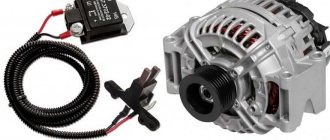
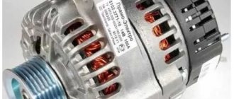
A generator of type 371.3701 is installed on the VAZ-21213 engine, and type 9412.3701 is installed on the VAZ-21214 engine.
These generators are structurally similar and are synchronous AC electrical machines with electromagnetic excitation, with a built-in rectifier based on silicon diodes and an electronic voltage regulator.
Technical characteristics of generators 371.3701 and 9412.3701
Generator type 371.3701
Direction of rotation (drive side) right
Generator type 9412.3701
Direction of rotation (drive side) right
The generator rotor is driven by a V-belt from the engine crankshaft pulley.
The stator and generator covers are secured with four bolts.
The rotor shaft rotates in bearings installed in the covers.
The lubricant placed in the bearings at the factory is designed to last the entire service life of the generator.
The rear bearing of the generator 9412.3701 is pressed onto the rotor shaft and is pressed by the rear cover through a plastic sleeve, the front bearing is pressed and rolled into the front cover and can only be replaced together with it.
Its inner race, together with the thrust ring and washer, is clamped by a nut between the pulley and the step on the rotor shaft.
The front bearing of the generator 371.3701 is secured with four screws between the inner and outer plates and can be replaced separately from the front cover.
The rear part of the generator 9412.3701 is closed with a plastic casing with latches.
On the back cover of the generator 371.3701 there is a casing with a rubber air intake, which allows you to take air for cooling the generator from the upper part of the engine compartment, which reduces the likelihood of water getting into the generator when driving through deep puddles and fords.
On the 21214 engine, this danger is less, since instead of a mechanical fan of the cooling system (which inevitably sprays water), electric fans are installed there, and they are located in front of the radiator.
The generator stator contains a three-phase winding made in a star configuration (the terminals of the phase windings have a common point).
The second ends of the phase windings are connected to a rectifier bridge consisting of six silicon diodes (valves) - three “positive” and three “negative”.
The valves are pressed into two horseshoe-shaped aluminum holder plates in accordance with the polarity (positive and negative - on different plates); one of the plates also contains three additional diodes, through which the excitation winding of the generator is powered after starting the engine. The plates are combined into a rectifier unit mounted on the rear cover of the generator (under the plastic casing of the generator 9412.3701).
The excitation winding is located on the generator rotor, its leads are soldered to two copper slip rings on the rotor shaft.
Power is supplied to the field winding through two carbon brushes.
Alternator slip rings 9412.3701 have a reduced diameter - this reduces the peripheral rotation speed and reduces brush wear.
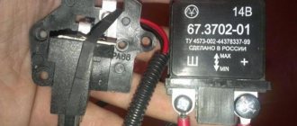
The brush holder is structurally combined with the voltage regulator and is mounted on the back cover of the generator.
The voltage regulator is non-separable; if it fails, it is replaced.
Until 1996, for the 371.3701 generator, the brush holder and voltage regulator were separate units (the control voltage from terminal “30” of the generator was supplied to terminal “B” of the voltage regulator).
Now voltage is supplied only to terminal “B” (terminal “B” is missing). According to their characteristics, the new and old voltage regulators are the same and, when assembled with a brush holder, are interchangeable.
To protect the on-board network from voltage surges during operation of the ignition system and reduce interference with radio reception, a capacitor with a capacity of 2.2 µF + -20% is connected between the terminals of the “positive” and “negative” valves (between the “+” and “ground” of the generator), located on generator rectifier block 9412.3701 and generator rear cover 371.3701.
Problems with the generator
The most common malfunction of this unit is brush wear. At the initial stage, it manifests itself as periodic power surges. Symptom: the charging control lamp on the instrument panel blinks periodically - the battery charging indicator lamp, because charging is either there or not.
On a note! Often, brush failure occurs on the fly without any blinking. Yesterday everything worked, today the generator is not breathing.
On a VAZ 2121, the brush block is attached to the generator with one screw and connected to the relay-regulator using knife terminals, the condition of which is also very advisable to check.
In all other Niva car models, the brushes are made in one unit with a relay regulator. Car enthusiasts who consider themselves cool “brewed” call this block “chocolate”.
Remove the back cover of the generator. We disconnect the wires from the brushes (VAZ 2121) and “chocolate” (other models), take out the block and assess the condition of the brushes. They should not be burnt, crumbled at the edges or protrude from the body by less than 5 mm. If something is not right, we change it.
The next problem is wear on the slip rings of the generator rotor. Quite “adult” cars suffer from this disease. Remove the back cover from the generator and carefully inspect the rings.
If they are in bad condition, we replace them. You can see how to replace the slip ring block in the video below.
Replacing the Niva generator rotor slip ring block
The next malfunction is the failure of rectifier or additional diodes. In order to check them, you will have to disconnect all stator windings. They are connected to the diodes using screw lugs.
We unscrew, remove, and test each diode with a multimeter set to diode testing mode. In direct connection, the device should show several hundred Ohms, in reverse - an infinitely large resistance. If this is not the case, change the diodes. Since the semiconductors are pressed into metal plates in the form of a double horseshoe, which are radiators and conductors, you will have to change the entire group of diodes along with the “horseshoe”. Additional diodes can be changed one at a time using a soldering iron.
Expert opinion
Alexey Bartosh
Specialist in repair and maintenance of electrical equipment and industrial electronics.
Ask a Question
To check the diodes, it is enough to disconnect the windings; there is no need to unsolder additional diodes. They will not interfere with the continuity of the rectifier diodes and will themselves ring perfectly.
Well, the last malfunction is a break or breakdown of the stator or rotor windings. We remove the brushes, turn off the windings and check them with an ohmmeter for breaks and short circuits to the housing. In addition to a break and a short to the housing, an interturn short circuit is possible. Without special equipment, it is impossible to detect a short-circuited turn, so you will have to limit yourself to only estimating the resistance and the lack of connection with the generator housing.
In the video below you can see how the field winding is checked using an audio test.
Continuity of the generator excitation winding
Generator check
Turn on the high beam headlights, heated rear window, and heater fan.
Measure the voltage at the battery terminals, which should be above 13.2 V for generator 9412.3701 and 13.6 V for generator 371.3701.
If this is not the case, the voltage regulator with the brush assembly, the generator windings are faulty (open or shorted) or the contact rings of the field winding are oxidized.
To ensure that the voltage regulator is working properly, turn off all consumers except the high beam headlights and measure the voltage again. It should be between 13.2–14.7 V for the 9412.3701 generator and 13.6–14.6 V for the 371.3701 generator.
The removed generator voltage regulator 9412.3701 can be checked by connecting a lamp (1–5 W, 12 V) between the brushes, and a power source to the “D+” and “ground” terminals (DC only, “minus” to ground!) , initially with a voltage of 12 V, and then 15–16 V.
In the first case, the lamp should be on, in the second - not. If the lamp lights up in both cases, there is a breakdown in the regulator; if it doesn’t light up, there is a break or broken contact between the brushes and the regulator terminals.
In both cases the regulator should be replaced. To check the generator regulator 371.3701, the current source should be connected to terminals “B” and “C” (“plus”) and “ground” (“minus”).
To check the valves of the rectifier unit, disconnect the wires from the battery, generator and from the voltage regulator terminal(s). Connect the “plus” of the battery through a lamp (1–5 W, 12 V) to the “B+” terminal of the generator 9412.3701 (to terminal “30” of the generator 371.3701), and the “minus” to its body. If the lamp is on, then there is a short circuit in both the block of “positive” and the block of “negative” valves.
To check the short circuit in the “positive” valves, connect the “plus” battery through a lamp to the “B+” terminal of the generator 9412.3701 (with the “30” terminal of the 371.3701 generator), and the “minus” - to the terminal of one of the phase windings of the stator. If the lamp is on, one or more positive valves are broken.
To check the short circuit in the “negative” valves, connect the “plus” of the battery through a lamp to the terminal of one of the phase windings of the stator, and the “minus” to the generator housing.
If the lamp is on, one or more negative valves are broken or the stator windings are shorted to the generator housing.
To prevent short-circuiting of the windings, remove the generator from the car and, having disconnected the windings from the voltage regulator and rectifier unit, check their short circuit to ground with a lamp or ohmmeter.
The generator valves can also be checked with an ohmmeter without connecting the battery and test lamp.
The short circuit of additional diodes can be checked by connecting the “plus” of the battery through a lamp to terminal “D” of the generator 9412.3701 (to terminal “61” of the generator 371.3701), and the “minus” - to the terminal of one of the phase windings of the stator (to one of the mounting bolts of the rectifier unit ).
If the lamp is on, one or more additional diodes are broken.
A break in the main valves is determined by a sharp decrease in the output current (voltage drop under load). This may also be caused by an open or shorted circuit in the generator windings.
A break in the additional valves can be determined by the low voltage on plug “D” of the generator 9412.3701 or plug “61” of the generator 371.3701 (below 14 V) at low and medium speed of the generator rotor.
The serviceability of each diode (main or additional) can only be determined with a removed rectifier unit using an ohmmeter or a test lamp. If the rectifier unit fails, it is recommended to replace it as an assembly.
It is possible to replace individual valves, but the main valves will require repressing them in the holder - an operation that requires care and skill.
The stator and rotor windings are checked with a special flaw detector or electronic oscilloscope - according to the shape of the voltage curves.
Source
371.3701 is installed on the VAZ-21213 carburetor engine 9412.3701 is installed on the VAZ-21214 injection engine . These generators are structurally similar and are synchronous AC electrical machines with electromagnetic excitation, with a built-in rectifier based on silicon diodes and an electronic voltage regulator. The generator rotor is driven by a V-belt from the engine crankshaft pulley.
Generator 371.3701
1 – clamping sleeve; 2 – bushing; 3 – buffer sleeve; 4 – protective casing; 5 – screw for fastening the rectifier unit; 6 – rectifier block; 7 – rectifier block valve; 8 – capacitor; 9 – rear bearing of the rotor shaft; 10 – slip rings; 11 – rotor shaft; 12 – brush connected to terminal “B” of the voltage regulator; 13 – pin “30” for connecting consumers; 14 – brush connected to terminal “Ш” of the voltage regulator;
15 – terminal “B” of the voltage regulator; 16 – voltage regulator; 17 – output “61” of the generator; 18 – stud securing the generator to the tension bar; 19 – impeller; 20 – pulley; 21 – bearing mounting plates; 22 – thrust ring; 23 – front rotor shaft bearing; 24 – rotor winding; 25 – rotor pole piece; 26 – stator winding; 27 – stator; 28 – front cover (drive side).
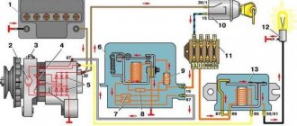
Generator connection diagram 371.3701
1 – Battery; 2 – generator; 3 – instrument cluster; 4 – resistor 51 Ohm, 5 W; 5 – diode;
6 – battery charge indicator lamp; 7 – fuse block; 8 – ignition relay; 9 – ignition switch.
Generator 9412.3701
17 – nut; 18 – rotor shaft; 19 – conical washer; 20 – washer; 21 – rotor pole pieces; 22 – stator core; 23 – bushing; 24 – rotor winding; 25 – rear bearing of the rotor shaft; 26 – bearing sleeve; 27 – slip rings; 28 – brush holder; 29 – stator winding terminals; 30 – additional diode; 31 – pin “D” (common pin of additional diodes).
| 1 – casing; 2 – output “B” for connecting consumers; 3 – capacitor; 4 – common terminal of additional diodes (connected to terminal “D” of the voltage regulator); 5 – holder of positive diodes of the rectifier unit; 6 – holder of negative diodes of the rectifier unit; 7 – positive diode; 8 – negative diode; 9 – voltage regulator; 10 – back cover; 11 – tightening screw; 12 – front cover; 13 – stator winding; 14 – thrust ring; 15 – front rotor shaft bearing; 16 – pulley; | |
Technical characteristics of generator 371.3701
Technical characteristics of the generator 9412.3701
The stator and generator covers are secured with four bolts. The rotor shaft rotates in bearings installed in the covers. The lubricant placed in the bearings at the factory is designed to last the entire service life of the generator. The rear bearing of the generator 9412.3701 is pressed onto the rotor shaft and is pressed by the rear cover through a plastic sleeve, the front bearing is pressed and rolled into the front cover and can only be replaced together with it. Its inner race, together with the thrust ring and washer, is clamped by a nut between the pulley and the step on the rotor shaft. The front bearing of the generator 371.3701 is secured with four screws between the inner and outer plates and can be replaced separately from the front cover. The rear part of the generator 9412.3701 is closed with a plastic casing with latches. On the back cover of the generator 371.3701 there is a casing with a rubber air intake, which allows you to take air for cooling the generator from the upper part of the engine compartment, which reduces the likelihood of water getting into the generator when driving through deep puddles and fords. On the 21214 engine, this danger is less, since instead of a mechanical fan of the cooling system (which inevitably splashes water), electric fans are installed there, and they are located in front of the radiator.
The generator stator contains a three-phase winding made in a star configuration (the terminals of the phase windings have a common point). The second ends of the phase windings are connected to a rectifier bridge consisting of six silicon diodes (valves) - three “positive” and three “negative”. The valves are pressed into two horseshoe-shaped aluminum holder plates in accordance with the polarity (positive and negative - on different plates); one of the plates also contains three additional diodes, through which the excitation winding of the generator is powered after starting the engine. The plates are combined into a rectifier unit mounted on the rear cover of the generator (under the plastic casing of the generator 9412.3701).
The excitation winding is located on the generator rotor, its leads are soldered to two copper slip rings on the rotor shaft. Power is supplied to the field winding through two carbon brushes. Alternator slip rings 9412.3701 have a reduced diameter - this reduces the peripheral rotation speed and reduces brush wear. The brush holder is structurally combined with the voltage regulator and is mounted on the back cover of the generator. The voltage regulator is non-separable; if it fails, it is replaced.
Until 1996, for the 371.3701 generator, the brush holder and voltage regulator were separate units (the control voltage from terminal “30” of the generator was supplied to terminal “B” of the voltage regulator). Now voltage is supplied only to terminal “B” (terminal “B” is missing). According to their characteristics, the new and old voltage regulators are the same and, when assembled with a brush holder, are interchangeable.
When the ignition is turned on, voltage is supplied to the excitation winding of the generator (terminal “D” of generator 9412.3701 and “B” of generator 371.3701) through a control lamp in the instrument cluster (the lamp is lit) and resistors connected in parallel to it. After starting the engine, the excitation winding is powered by additional diodes of the rectifier unit (the control lamp goes out). If the lamp lights up after starting the engine, this indicates a malfunction of the generator or its circuits.
The “minus” of the battery should always be connected to the “ground” of the car, and the “plus” to terminal “B” of the generator 9412.3701 (terminal “30” - generator 371.3701). Switching back on will lead to breakdown of the generator valves.
It is not recommended to disconnect the battery when the generator is running (especially on engines equipped with an injection system). The resulting voltage surges in the on-board network can damage the electronic components of the circuit.
The generator valves (and other devices in the vehicle’s on-board network when the generator is connected) should be checked at a voltage no higher than 14 V; a higher voltage (for example, when checking with a megger) can cause damage to the valves. If it is necessary to check the insulation of windings with high voltage, the generator should be removed, and the winding terminals should be disconnected from the rectifier unit and voltage regulator.
Generator replacement
https://www.youtube.com/watch?v=Mu0Cd5iBH5U
To repair or replace the generator, the car owner will have to remove the unit completely from the car or turn to professionals for work. If you still want to carry out the replacement yourself, then first you will need to prepare all the necessary tools:
- hammer;
- extension;
- keys to "10" and "19".
The procedure consists of the following sequence of actions:
- First, you will need to park the car in a place designated for inspection and repair. The car will also need to be secured using special wheel chocks. Finally, in order for the work to be carried out safely, you should disconnect the battery by disconnecting the terminals from it.
- After this, you need to remove the engine protection. It is attached to several bolts, and they must be unscrewed to get to the lowest bolt of the generator.
- After this, you will need to knock out the mounting bolt using a hammer. It is recommended to knock carefully so as not to damage the thread and to prevent the bolt from coming out in the opposite direction. A hammer is necessary, since a wrench or any other tool simply cannot handle a bolt.
- Next, you need to remove the bolt, swinging the generator from side to side. It is necessary to bolt in any case, as this makes it easier to remove the rod.
- The fourth step involves disconnecting the wiring. To do this, the power wires connected to the housing are disconnected from the unit. In this case, you can first disconnect the plug from the wires.
- Wires are also attached to the generator, tightened with a nut or bracket. In this case, the nuts must be unscrewed with a wrench, and then the loose wires must be pulled out.
- Finally, after disconnecting the wires, you can begin to unscrew the upper fastening element with the belt tensioner. For this you will also need a wrench, as well as a small extension cord.
- Disconnecting the fastener will allow you to remove the belt and alternator. Then you can start cleaning the vacated space with a brush and installing a new unit.
The structure is assembled in the reverse order; the entire procedure will take about two hours if you have all the necessary tools.
Additionally, it is worth noting that when everything is assembled, you will need to adjust the position of the generator using the tensioner. To do this, you need to unscrew the tensioner nut and tighten or loosen the belt, while observing the battery charge.
Also interesting: Chevrolet Niva camshaft sensor
If the indicator returns to normal, then the selected tension is sufficient. There is no need to tighten the structure, as the generator bearing may fail. If the tension is insufficient, the generator will work intermittently, and this can also lead to breakdown.