Mechanical pron
Once again, suddenly stubborn, I thought that the slider and distributor cap were sad and terrible and decided to assemble a more modern ignition system.
I won’t be able to explain the principle of operation better than Evgeniy Travnikov, whom I deeply respect, so the word is to him:
True, I do not agree with him on one thing, namely, the use of two Hall sensors and the resulting hemorrhoids with their exact relative position. The sensor output is made according to an open collector circuit, which makes it possible to assemble a simple inverter to control two switches in antiphase from one sensor. True, another hemorrhoid appears here: in this version, both edges of the rotor curtains are involved, so the curtains must be exactly 90 degrees, which does not happen in serial distributors; new ones must be made. Here such a system is implemented, however, the scheme for matching the sensor with the second switch will not work with every switch. At least it didn’t work out for me; at low speeds it was glitching and shooting into the jammer. Which is no wonder, the input impedance at the common emitter is nothing at all! (laugh here).
In general, this option works without glitches:
Of course, I needed to buy several devices from my beloved TAZ donors:
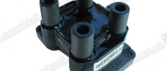
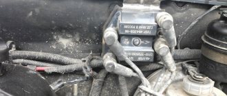
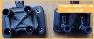
Ignition coil. seems to be from Kalina. It consists of two double-spark coils in one housing, which is ideal for a four-pot motor.
Switches for TAZ-2108, two pieces.
The distributor was converted to a Hall sensor, while I was waiting for the curtain blanks from the turner, I made a straight curtain with a file and deployed the sensor in order to somehow start the system.
To tie it all together, I wove a braid of wires. The small black box in the center of the frame contains just the signal inverter circuit for the second switch.
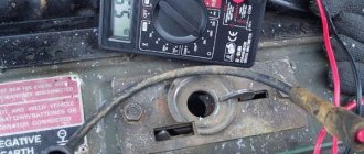
I assembled everything on the table and checked how it worked:
It’s gotten a little better at the low end, and it doesn’t adjust so fiercely anymore.
Installation of an ignition with two circuits, which is equipped with one or two hall sensors, is acceptable for any modern car with a new type toggle switch. The main thing is to have two switches on hand and use them to solve this issue. Although an option is acceptable when the driver has only one switch operating on a two-channel basis. In this case, dual-circuit ignition is installed on the classic without any problems.
There are several ways to install dual-circuit ignition. Photo: mp3-oblako.ru
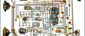
How did the distributors work?
The breaker-distributor has an internal shaft driven by the crankshaft, on which a dielectric rotor-runner with a rotating current-carrying plate is mounted at its end. A spring-loaded carbon brush slides along the plate, connected to a high-voltage central contact in the distributor cap, which, in turn, is connected to the secondary winding of the ignition coil. The current carrying plate periodically approaches the contacts of the high-voltage wires located in the distributor cover that go to the cylinder spark plugs. At this moment, a high voltage arises in the secondary winding of the coil, which breaks through two air gaps: between the current difference plate and the contact of the wire to this spark plug and between the electrodes of the spark plug.
On the same shaft there are cams, the number of which is equal to the number of cylinders, and the protrusions of each cam open, simultaneously with the connection of a specific spark plug, the current breaker contacts connected to the circuit of the primary winding of the ignition coil.
To prevent a spark from occurring between the contacts of the breaker when opening, a large capacitor is connected in parallel to them. When the contacts of the breaker open, the induced emf in the primary winding causes a charging current of the capacitor, but due to its large capacity, the voltage on it, and therefore between the open contacts, does not reach the value of the air breakdown.
Advantages of dual-circuit ignition
This ignition option has several components:
There are also additional parts, without which a correct system cannot be created:
- Good wiring to match new ignition.
- Various types of fastenings.
- Spark plugs with appropriate characteristics.
Such a system has its sides, both negative and positive.
- Increasing the maximum frequency of internal combustion engines.
- No resonant circuit.
- Increasing the voltage on the spark plugs to 22 kV.
- Improved sparking.
- Lack of centrifugal type voltage distributor.
- Increase in speed.
GAZ 31 ZMZ difficult 3 liters › Logbook › Distributor without a slider. Benefit for those who purchased the kit.
Hi all. I placed several orders for curtains for a runnerless distributor.
I decided to make a detailed post on how to properly assemble the system. The following people ordered. motonick dobriak1 solomon2302 voia-ka I made assembled distributors for two, and a complete ignition kit for one. 062711 roma742
First of all, you need to disassemble the old distributor. Remove the slider, remove the felt plug, if there is one. Unscrew the central screw, securing the shaft from turning by the lower “fork.” Remove the “rotor.”
Next, unscrew the 3 screws and remove the “stator”.
Under all this you can see the thrust of the ignition timing vacuum corrector drive. The old system pressed the rod with a “stator”
To secure the corrector rod, you need to remove it by unscrewing 2 screws from the outside of the housing. Then unscrew the 2 screws securing the bearing plate. At the same time, I advise you to wash the old bearing and fill it with new good lubricant. The bearing itself is rolled, do not even try to remove it. There is a hole in the bushing on which the corrector rod fits. You need to thread a small cotter pin or wire into it. I use a cotter pin. Replace the turntable.
Spread the cotter pin or secure it with wire. Otherwise, the traction will fly off.
Be sure to check the free rotation of the platform. To do this, you need to suck out the air from the vacuum corrector with your mouth.
In principle, you can then place a plate under the Hall Sensor and the Shutter. To fasten the plate, the original screws are a little short, for this I added elongated screws to the parcels.
You can go further, disassemble everything, wash it and lubricate it with good lubricant. To do this, you need to press the cotter pin out of the “fork” at the bottom of the distributor. When disassembling, do not lose washers; if necessary, you can add them to eliminate vertical play.
A new shaft was installed in one of the ordered distributors.
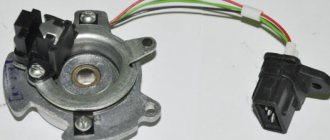
It is also necessary to make fasteners for the hall sensor. The slot from the old contact with a nut for a 7 key is suitable for this. It is better to use the sensor itself from the field. Such a hall sensor
. One of his ears needs to be cut off. Place it in the slot and mark the mounting location. Drill with a 3mm drill and cut an M4 thread.
In the photo, DH's ear has already been cut off.
It is better to stir the DH wire in the same way as in the photo
Next we install the DH plate. It can only be placed in one position.
The slot on the plate should face the DC terminals.
Next, depending on the curvature of the distributor, you may have to grind off the top of the sensor a little, just go through it with a file a couple of times. It's just plastic... Otherwise it might get caught by the curtain, but not necessarily. Inspect everything carefully during assembly.
The sensor itself will also need to be positioned outward from the center. The holes in the DH make it possible to do this a little. If there is not enough travel, the curtain may touch the corners of the curtain with its edges. They can be trimmed a little with a knife. But again, I repeat not necessarily. Look in your case.
Further, for proper operation and adjustment of the ignition angle, the drive must be positioned correctly. Place a mark on the pulley for the ignition installation in cylinder 1. The slot in the distributor drive for the fork must be strictly parallel to the axis of the engine. The slot is not seven-dimensional. The wide part should be facing the engine. If this is not the case, rearrange the drive; small deviations are acceptable. In short, it should be approximately as in the photo.
In the correct position, the curtain should stand like this.
Next you need to attach the curtain to the shaft. Lubricate the shaft with regular engine oil and install the curtain.
The central part of the shaft should be slightly higher than the inner hole in the curtain. I tried to make the curtains in such a way that I could simply tighten the central screw with one simple washer. In this case, the vertical play of the curtain should not be large. Generally up to 1mm is allowed, it will not affect anything. But if the curtain is clamped, the centrifugal ignition timing mechanism will not work. If the backlash is large, then you need to install wide washers, the ones that were there at the very beginning. They reduce vertical play. But they should not be clamped with a small washer and screw. It is better to install the screw with a washer and an engraver so that it does not unscrew. In order to tighten it, the shaft must be fixed.
Next you need to file the distributor cap. Remove the central graphite pin from the center inside.
Source
Video
Installation of an ignition with two circuits, which is equipped with one or two hall sensors, is acceptable for any modern car with a new type toggle switch. The main thing is to have two switches on hand and use them to solve this issue. Although an option is acceptable when the driver has only one switch operating on a two-channel basis. In this case, dual-circuit ignition is installed on the classic without any problems.
There are several ways to install dual-circuit ignition. Photo: mp3-oblako.ru
Refusal of high voltage distribution
The mechanical distributor of high-voltage voltage across the cylinder spark plugs remained in the commutator for the longest time. The most interesting thing is that this unit was quite reliable and did not cause any major complaints. However, time does not stand still, and at the beginning of this century, the switch connection diagram underwent another major change.
In modern cars, there is generally no distribution of high-voltage voltage from one coil to different spark plugs. On the contrary, the coils themselves “multiplied” in them and became an accessory to the spark plugs of each cylinder. Now, instead of contact switching of spark plugs at high voltage, contactless switching of their coils at low voltage is performed. Of course, this complicates the switch circuit, but the capabilities of modern circuit technology are much wider.
In modern cars with injection engines, the switch is controlled either by an autonomous engine control unit or by the car's on-board computer. These control devices analyze not only the crankshaft rotation speed, but many other parameters characterizing the fuel and coolant, the temperature of various components and the environment. Based on their analysis, the ignition timing settings also change in real time.
( 2 ratings, average 4.5 out of 5 )
Advantages of dual-circuit ignition
This ignition option has several components:
There are also additional parts, without which a correct system cannot be created:
- Good wiring to match new ignition.
- Various types of fastenings.
- Spark plugs with appropriate characteristics.
Such a system has its sides, both negative and positive.
- Increasing the maximum frequency of internal combustion engines.
- No resonant circuit.
- Increasing the voltage on the spark plugs to 22 kV.
- Improved sparking.
- Lack of centrifugal type voltage distributor.
- Increase in speed.
Installing dual-circuit ignition
This image will help you set the TDC. Photo: avtodvizhok.ru
- The first step is setting the TDC. This figure must be at least 4 cylinders. It is easy to see by the position of the special slider. When this is done, the crankshaft ratchet is rotated to the mark on the pulley.
- Old spark plugs and coils with tumblers are completely dismantled. The main thing is to remember the color of the wires that connect to the devices, as well as the order of operation.
- After this, they proceed to laying new wiring.
- The new high-voltage coil is installed first.
- Then there's Tumblr. It should stand exactly the same as the old one. There are slight differences in this indicator between different models. Only the height of the cylinder block can be different in certain systems. Depending on this, the appropriate length that the drive shaft must have is selected.
- The next step is attaching the switch. The engine compartment shield is an ideal place to mount this device.
- The candles are screwed in separately. Wires that support high voltage are put on.
- Wiring is connected.
How to replace the speed sensor and in what situation it will be needed - see our material.
Find out how to choose car shock absorbers and what to consider here.
About the features of dual-circuit ignition
Typically this type is installed on engines that operate and are sold in conjunction with carburetors. Thanks to this, it is possible to minimize the disadvantages that the corresponding types of motor have.
Changes can be felt immediately after the system has been installed. But is there any point in installing a new option? To answer this question, you need to understand everything a little deeper.
Find out how a dual-circuit system with one hall sensor works in this video:
Some switches have built-in devices and systems that allow you to monitor peak moments. And monitor the device when the energy ceases to be effective. The switch mode appears automatically in the switch to prevent the coils from getting too hot. For example, in normal mode, approximately 10 A is supplied. When operation is limited, the result is reduced by about half.
- The energy storage time is determined by the amount of current supplied through the coil.
- Voltage itself does not have its own time value. It depends on what voltage the on-board system operates at.
For example, when the engine is running, the on-board network produces an average voltage of 14 volts.
In the average coil, the maximum voltage accumulates in about three milliseconds. Photo: aliexpressin.ru
Everything happens at the moment when the circuit is closed and the coil is fully charged. The time has come to give a signal for sparking. We get the following results after calculations from standard mathematics:
- At engine speeds above 1000 units, 33 sparks occur per second.
- 30 milliseconds in this situation is the time interval from the formation of one spark to the next.
- It takes three milliseconds for the coil to charge. And there is only one spark for the combustion process.
- We get a total cycle of 4 milliseconds. This makes it possible to quickly supply additional charges to the coil.
The coils perform best when the speed level is maintained at up to 6 thousand units. In this case, the device fires approximately 200 times per second. This means the cycle is up to 5 milliseconds. There is enough time for the device to ignite quickly and continue to work as efficiently as possible.
Proven ignition circuits
The main thing during work is to check the standard diagrams. Or with the option that the user himself chose in this or that case. Only after completing a complete check can you proceed to starting the engine. You must make sure that the position and operation of the parts fully correspond to the diagram.
For greater clarity, you can use this diagram. Photo: ha.d-cd.net
Most of the work in this direction is related to electrical network components. This means that without minimal information in this area, it is better not to start the process at all.
And another version of the 2-circuit ignition circuit.
Some people support dual-circuit systems, while others evaluate them very critically. This system can work as a middle option between other devices on the market. For the most part, it is used to improve the existing motor. And as an alternative to engines that run on injectors. Over time, it is double-circuit devices that become more and more reliable and of high quality. With a higher compression ratio, they will also be a good option, capable of providing high efficiency in all conditions.
Lada 2109 Inestra › Logbook › 2-circuit ignition (from A to Z)
Good day to all! I’ve been collecting material for this post for a very long time, I hope it will be interesting and you won’t kick me) Let’s talk about 2-circuit ignition.
My inspiration was Pashka and his little boy). But even the inspiration was not enough to decide and start. I went through a bunch of waste paper and sources. I re-read a bunch of posts. And yet he began to act. But the eyes are afraid of the hands! - I love this expression! After the ignition wiring harness was removed as a result of manipulations with a side cutter and “such and such a mother,” I began to think a little about whether it was worth it? But I really didn’t want to put this “kaka” back. While dismantling the harness, the wiring harness leading to the diagnostic block also caught. I’ve been dreaming of getting rid of it for a long time, here’s the reason)…Delete!
Go ahead. It's time to braid... or rather, make a “braid” for ignition. I reviewed a lot of different schemes. I settled on this one. I’ll explain why, the contacts of the switches, EPHH and DH are numbered, it helps a lot when making the braid and assembling the connectors.
Damn! What about Eastern wisdom? I order corrugation and all sorts of different connectors so that the wiring is in accordance with “Feng Shui”).
Everything seems to be clear with the wiring.
We're probably moving on to the most tedious and difficult part... yes, yes, a distributor.
I started working on the distributor only when I had collected spare parts to assemble another one, if necessary.
Positioning the sensors is not so easy, I made a template that was supposed to simplify positioning - it simplified it, but not much).
I will dwell on a few points: 1. it is advisable to have an M5 tap No. 3, I personally sacrificed No. 1. 2. We saw off the heads of two bronze bolts for fastening the DH (I don’t understand why no one talked about this? They rest against each other!). 3. for adjustment, you can take old DHs and chop them up, so that you know how to then chop up new ones). I won’t even dwell on the curtains - they cut it off and forgot about it. 4. and most importantly! No one is talking about the fact that you will have to trim the bearing housing of the pad so that the wires do not catch on anything when the vacuum corrector is working.
After all this, I decided to check the operation of the system as Travnikov advises.
It seems to be the norm, although I’m a layman in such matters(. Let’s move on to the coils. Where should we put them? I settled on the option near the tank, installed a new tank with 2121, and thus freed up space for the KZ knoshtein, which, after shamanism over a sheet of 3mm iron, began to look like So.
The time has come to stretch out the “vermicelli”, but damn, the standard engine compartment is finally ok, and I like it when the hood is raised, and then “Lala”.
I take out the engine compartment, pour it over, insulate it here and there, into the corrugation, and put it back in place.
And after that I run a new ignition wiring harness. I won’t dwell on mounting the switches, there’s nothing special there. Let me just say that at first I thought about installing the switches 0729, but after the purchased new 0729 turned out to be a “corpse”, I returned to 0529. DH made in Kaluga and KZ SOATE - this is the config. Cheap but cheerful.
Time is ticking towards the first launch.
Nerves to the limit! START!
Nothing!
I drained the already dead battery. I went out and looked around, your division! There is no auto choke! A week later I charged the battery, whack-whack-whack... YES
. This is happiness! After three months of manipulation, prayers, shamanic spells and love spells, the idea degenerated!
Unfortunately, I can’t give feedback on the driving performance, but the ease of starting is obvious! I don't remember it starting up so easily. I'm happy. Expect reviews of all winter improvements in the extended post. When I don’t know))). It seems like everything, don’t switch gears, there’s a lot of interesting things ahead! I will answer all questions.) Thank you everyone for your attention! Good luck and patience)