- What's included in the rear suspension?
- Disassembling and replacing the rear suspension: instructions
- Front suspension device
- Disassembling and replacing the front suspension: instructions
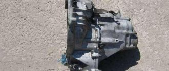
A complete set of VAZ 2114 chassis elements
The chassis of the car includes two suspensions - front and rear. During operation of the machine, most of the load falls on the chassis. The quality and comfort of the ride, as well as the safety of the driver and passengers, depend on the condition of the front and rear suspensions. The main function of each suspension is to eliminate vibrations and soften the ride. Also, the tasks of the chassis include reducing roll when turning, ensuring a smooth ride, and providing high information content for the driver in the city and on the highway.
On the roads of the CIS countries, the chassis is subject to excessive load, since the condition of the road surface leaves much to be desired. As a result, motorists often turn to car service centers. Things are better with the VAZ 2114, since it has more modern systems compared to previous Lada models. Many motorists choose to solve the problem on their own. But in order to understand what has gone wrong, you need to know the suspension structure.
What's included in the rear suspension?
The image below shows all the main elements of the rear suspension that can fail.
Rear suspension diagram of VAZ 2114
- The first part is a rubber-metal hinge, which is the main attachment to the car body.
- A bracket used to secure the rear suspension arm to the body.
- Shock absorber housing.
- A buffer that takes the load from the compression stroke.
- Casing cover.
- Main support washer.
- Shock-absorbing cushion.
- Spacer sleeve.
- Strut (shock absorber).
- Insulation gasket.
- Solid spring.
- Connecting element for levers.
- Beam lever.
- Bracket for fastening the rack structure.
- Flange.
- Lever bushing.
The beam structure includes a connector and two trailing arms; these elements are indicated in the diagram as numbers “12” and “13”. The parts are fastened together by welding. In the rear part, flanges (number “15”) and brackets for attaching struts (shock absorbers) are attached to the levers. The axles of the rear pair of wheels along with the brake elements are screwed to the flanges. Bushings (16) are installed on the rear suspension arms at the front. They are fastened using rubber-metal hinges - number “1”. One end of the spring rests on the support through a rubber gasket, and the other on the shock-absorbing cup.
Chassis of VAZ 2114: description, repair
Fundamentally, the chassis designs of front-wheel drive VAZ cars of various models are similar to each other, however, there are differences. It will be useful for car enthusiasts to understand the question of what the VAZ 2114 suspension consists of, to know the causes and types of malfunctions, and to be able to eliminate them.
Front suspension device
Suspension type: independent, telescopic. Let's take a closer look at the main components and elements that make up the front suspension of the VAZ 2114.
- The basis is the main rotating support element - the front pillar. Assembled into a single unit with a cylindrical spring, a swivel bearing, and upper and lower support cups. The strut is attached to the steering knuckle of the hub with the lower bracket, secured to the body with three bolts at the top and rests against the glass with the upper cup. Has a steering knuckle for attaching a tie rod pin.
- Front hub assembly with ball joint, double row bearing, brake disc and caliper. The ball joint is fixedly screwed to the lower suspension arm, the support pin is inserted into the seat at the bottom of the hub and screwed with a nut.
- The lower suspension arm is attached to a brace, which is attached at both ends to the body side member using two brackets. On one side of the brace there is an attachment point for the anti-roll bar, in which one end is fixed. The second end of the stabilizer is fixed to the suspension extension of the second front wheel, thus connecting them together.
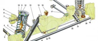
Front suspension diagram for VAZ 2114
The wheel is turned by a steering rod, which pulls the eye on the stand and turns the entire assembly, while at the top it turns on a support bearing, and at the bottom on a ball joint. The anti-roll bar ties the suspension on both sides together and makes it work in sync.
Rear element design
Suspension type: dependent, on a rigid transverse continuous beam. The structural elements of the rear suspension and the methods of their connection in the VAZ 2114 are as follows.
- The base is a cross beam. The structure is welded, in the shape of the letter “H”, only with a long cross member. The two front ends of the beam are secured to brackets bolted to the rear side members of the vehicle. The method of connection to the brackets is hinged, on rubber-metal bushings. The rear ends of the beam have mounting flanges for wheel hubs. The hubs are bolted to the flange; a protective casing, brake cylinder and pads are mounted on them. Inside the hub there is a double row radial bearing. The brake drum is mounted on top of the pads and secured to the hub with guide pins.
- The lower end of the strut with a cylindrical spring is attached to the rear ends of the beam on the other side of the hubs. The upper end of the shock absorber rests against a glass welded to the body through a rubber spacer.
Rear suspension diagram for VAZ 2114
The rear suspension diagram is shown in Fig. 2. The rear chassis of the VAZ 2114 car operates as follows: the transverse beam works like a swinging pendulum, the attachments to the side members do not allow it to move along the axis of the car. Racks with springs attached to the opposite end of the pendulum limit its up-and-down movement and serve as a shock-absorbing and partially supporting element for the wheels.
Brief description of faults
In most cases, chassis repairs can be done yourself. The main malfunctions, as a rule, are associated with the failure of the shock-absorbing front and rear struts, since they are the most loaded structural element. The racks absorb dynamic loads from the car body, from the wheels when overcoming uneven road surfaces and lateral loads from the influence of steering rods, which increases at low speeds.
Two tools are required to remove and install the stands. The remaining tools are in every car enthusiast's garage:
- spring ties;
- a puller for pushing the steering rod pin out of the lever; it can also be used to press out the ball joint if necessary.
Smaller suspension malfunctions occur due to wear of the rubber seals and rubber-metal bushings (silent blocks). They are much easier to replace than a stand, although sometimes a device is also needed to press out silent blocks.
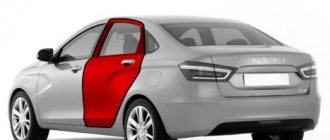
Disassembling and replacing the rear suspension: instructions
The main parts of the rear suspension are highlighted in color
A complete disassembly of the rear suspension is required if the motorist decides to lubricate all the parts or change them. Most often you need to get to a specific element and replace it. The parsing proceeds as follows:
- The VAZ 2114 is installed under an inspection hole, or, as an option, on a lift. In the luggage compartment, the rear and side trims and the seat belt retractor are disconnected. Also in the luggage compartment there are fastenings for the racks to the car body. They need to be loosened; there is no need to unscrew them completely.
- Next, the fastenings of the rear wheel pair are loosened. To do this, you need to remove the hubcaps and then completely dismantle the wheels. Reliable jacks should hold the car at this time; they are usually installed on each side.
- Now it is necessary to dismantle the brake system cables. You need to get them assembled. To do this, the cable fastenings to the suspension arms and the body of the VAZ 2114 are disconnected. Afterwards, the brake drums are dismantled. The cable ends should be removed from the manual drive levers. You also need to disconnect the flanges from the brake flaps.
- Before dismantling the hoses and pipes of the brake system, care must be taken to prevent leakage. Next, you need to dismantle the elastic drive lever, which is used to operate the brake pressure regulator. To remove the lever, you need to disconnect it from the bracket by removing the lock washer, then remove the shackle from the wheel axle.
- The next step is to disconnect the struts (shock absorbers). To do this, remove the rubber cushions, nuts attaching to the body part and the washer. After this, you need to install additional stops for the front wheelset. The rear part should be raised. After this, you can remove the compression stroke buffers, springs and shock absorber covers.
- If you disconnect the body mounting brackets, the entire beam can be detached. The rear suspension along with the struts will lie in front of the motorist. If necessary, you can disassemble the shock absorbers, which is no longer difficult.
Components of the rear pillar of the VAZ 2114
IMPORTANT. The shock-absorbing spring must be removed using special ties. If they are not used, serious injury may occur as the iron spring is under high pressure.
Detailed suspension repair diagram
So, let's look at a brief diagram of how to disassemble the suspension of a VAZ-2114 car:
- The car must be placed on a lift. Of course, you can use the inspection hole, but this is quite inconvenient and not entirely safe, since dismantling will be carried out on both sides at the same time.
- The first step is to dismantle the caps (if any), disks and loosen the wheel bearing fastenings.
- Next, disconnect the ball joint and also remove the steering rod.
- Unscrew the fastening and remove the stabilizer.
- The next step is to dismantle the lever.
- We remove the caliper.
- We remove the outer CV joint from the hub.
- Now you can remove the brake drum from the steering knuckle mountings.
- We dismantle the steering knuckle.
- Remove the shock absorber strut assembly.
- We disassemble the removed parts.
- Assembly is carried out in reverse order.
Thus, the entire suspension assembly can be replaced. If we take time, then complete disassembly of the VAZ-2114 suspension will take approximately 8-12 hours, if no difficulties arise. Some “kulibins” make it easier to speed up the process, and if the suspension to be removed will no longer be installed. It is worth noting that this method is dangerous and contrary to safety regulations, especially if the motorist has never performed this process. Let's briefly look at how the accelerated process occurs:
- Unscrew the stabilizer.
- We dismantle the upper mount of the shock absorber struts.
- Unscrew the steering rod and brake hoses.
- Carefully unscrew the lever mount.
- The suspension feeds downwards in the assembly.
Tuning
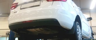
Tuning suspension for VAZ-2114
Many motorists, in order to improve the stability and maneuverability of the car, install a sports version of the suspension, both rear and front.
It fits perfectly into the seats and is attached to the body without requiring any modifications. The sports suspension has greater stability and maneuverability, and can also withstand a load on the suspension that is 2 times greater than the standard one. The cost of this option is about 30-40 thousand rubles.
Tuning suspension installed on a car
Front suspension device
The main element of the front chassis of the VAZ 2114 is the shock absorber strut, which is designated as number “9”. It is attached to the steering knuckle with two bolts. Compared to the rear system, the front suspension has a more complex design, which can be understood by the number of parts. Number “11” indicates a bolt that passes through the holes of the rack bracket; it has an eccentric washer and an eccentric collar. When the steering gear turns, the top bolt turns. The result is that the car turns. Most often, shock absorber struts fail, since they do the main job.
Diagram and explanations for it
Lada 2115 *****KRASAVITSA***** › Logbook › Front suspension
Good day everyone! Now we got around to the front suspension, before that we bought all the spare parts for the front suspension
tuning of the front suspension of the VAZ 2115, modification of the chassis of the VAZ 2113-2115Replacement of shock absorbers and springs of the front suspension of the VAZ 2114, VAZ 2115, VAZ 2113, Lada Samara 2
Springs (and shock absorbers on Lada 2115) should only be replaced in pairs (on the front and/or rear axle).
We carry out the work on an inspection ditch or overpass, but it is also possible on a flat horizontal platform.
To replace the springs and shock absorbers of the front suspension, remove and disassemble the guide spring strut.
There are two options for removing the guide spring strut of the VAZ 2113. In the first option, it can be dismantled as an assembly with the steering knuckle and brake disc without loosening the nuts of the lower and upper (adjusting) bolts securing the strut to the steering knuckle. This option is convenient if, after completing the work, you do not plan to adjust the angles of the front wheels.
But since after replacing shock absorbers, steering tips and springs it is necessary to adjust the wheel alignment angles, we will consider the second option.
We hang and remove the wheel from the side of the rack being removed. Turn the steering wheel in the opposite direction until it stops. Remove the cotter pin...
Use a puller to press the pin out of the lever. If there is no puller, unscrew the nut not completely, insert a mounting blade into the spacer between the steering rod and the strut lever, and hit the end of the strut lever with a hammer.
When subsequently installing the spring strut guide, aligning the marks does not guarantee accurate setting of the specified wheel camber angle, but allows for a slight deviation from the original value.
Using a 19mm socket, unscrew the nut of the upper bolt, holding the bolt from turning with a wrench of the same size.
We remove the rod with the working cylinder from the strut body and drain the shock absorber fluid into a container.
Install the spring with ties on the lower support cup of the strut.
We install the upper support cup of the spring, the upper support, attach and tighten the rod nut with a special wrench. Remove the spring clamps.
We recommend adjusting the angles of the steering wheels at a service station. THIS is the rubbish that I changed =)
ATTENTION ! A twin-pipe shock absorber that is not pumped before installation is a common cause of failure of the shock absorber piston system. This is a violation of the installation instructions and a possible reason for a non-warranty case! If air remains in the inner liner of the shock absorber, the shock absorber may not perform its function correctly.
Failure to operate leads to noise, knocking when the shock absorber operates and its possible failure.
Based on long-term work experience, engineers of the Samara-Lada OJSC company have prepared optimal recommendations for shock absorber pumping technology:
Before installing a twin-tube shock absorber on a car, it must be brought into working condition. During transportation and storage, in twin-pipe shock absorbers, the working fluid can flow from the inner to the outer cylinder, and boost gas enters the inner cylinder. In this case, the shock absorber will make knocking noises when operating in the car’s suspension, and its throttle valves will be destroyed. To avoid damage to the shock absorber, it MUST be brought into working condition (pumped) before installation. For this:
1) Turn the shock absorber over with the rod down and compress it smoothly, without jerking;
2). Fix the shock absorber rod in this position for 2-3 seconds;
3). While holding the rod, turn the shock absorber over with the rod up, fix the shock absorber in this position for 3-6 seconds;
4) Keep the shock absorber in a vertical position for the specified time and smoothly extend the rod to the end of the stroke;
5). Turn the shock absorber over with the rod down and pause for 2-3 seconds. and repeat operations 1, 2, 3, D 5-8 times;
6) Having finished pumping the shock absorber, following the sequence, stop at step 4;
7) Holding the shock absorber vertically, with the rod up, perform a control operation (with sharp but short movements of the rod, make sure that the piston moves smoothly, without failures). A well-pumped shock absorber means smooth piston movement without failure.
After pumping, the shock absorber should be in the working position, with the ROD VERTICALLY UP, until it is completely installed on the car. I am completely satisfied with the suspension! =) Thank you all for reading the entire post to the end! Thank you all for your attention! Good luck to everyone on the roads!
Disassembling and replacing the front suspension: instructions
- The VAZ 2114 is installed on a viewing hole or raised on a lift. The car must be set to the parking brake. It is necessary to remove the wheel caps, loosen the mounting bolts and unscrew the hub nut. Having secured the front of the car, you can remove the front wheels.
- Next, you need to remove the ball joint pin, which is located in the swing arm of the front strut. The next step is to remove the front stabilizer link (number “24”) from the front suspension arm (number “22”). Next, the stretch marks from the body (30) are removed. Next, you need to completely disconnect the ball joint that is attached to the steering knuckle.
- Now you can remove the front suspension arm. To do this, you need to disconnect it from the body bracket (28). Afterwards the lever is removed along with the bracket and the extension (29, 30). It is also necessary to remove the bolts that secure the pads to the steering knuckle.
- In front of the driver there will be a caliper assembly. To avoid problems with it, you do not need to completely remove it; you need to hang the caliper on a hook in such a way that there is no load on the main hose. The next step is to press the spline shank out of the front wheel hub.
- From the side of the engine compartment, you need to remove the protective fist (“41”). To do this, unscrew the telescopic strut nuts and then remove the solid front suspension strut. It should be together with the wheel hub and steering knuckle. The other front suspension strut is removed in the same way. Next, the racks are removed from the rod.
Removing springs using zip ties
When removing the bolts that secure the ball joint to the steering knuckle, you must use a socket wrench. Otherwise, the protective cover of the hinge may be seriously damaged, resulting in additional costs.
In the case of the front suspension, its assembly proceeds in the reverse order, with the exception of a few features. When installing the mounting bracket to the VAZ 2114 body, you need to make sure that the threads of the bushings are not damaged. To do this, you must perform operations carefully. Also, longitudinal displacement of the cushions on the bar must not be allowed. This can happen during installation of the anti-roll bar.
How does the ball joint change?
To do this, you need to remove the front wheel mounting bolts and hang part of the car on a jack. Next, the nut securing the ball element is unscrewed. The support pin is pressed out of the lever. Similar to the previous case, this is done using a puller. If there is none, do not unscrew the nut completely.
Also interesting: Recommended tire and wheel sizes for Lada 4×4 » Lada.Online - all the most interesting and useful about LADA cars
After this, the lever is moved to the side (with a pry bar), and the support is successfully pulled out. A working finger should not move with more than 0.8 millimeters of play in the support. Otherwise, it needs to be replaced, since there is a large output here. Before installing the dirt boot, it is recommended to coat the surface of the support with sealant.
Read news about the new Niva
- Lada 4×4 Bronto - sales stopped, new details » Lada.Online - all the most interesting and useful about LADA cars
- Description of the instrument panel Lada 4×4 (VAZ 2121, 2131) » Lada.Online - all the most interesting and useful about LADA cars
- Chevrolet Niva gasoline consumption per 100 km
- Buy LADA (VAZ) 2131 (4×4) 2021 in Rostov-on-Don, low price for Lada 2131 (4×4) 2021 on the Avto.ru website
- Fuses Niva 21214 injector «
- The new large Lada 4×4 Niva “Bigster” 2021-2022 based on the Dacia Bigster was shown for the first time. The SUV has changed beyond recognition
- New Niva Chevrolet Lux 2021 - review of GLC equipment
- Niva Chevrolet alarm connection points "