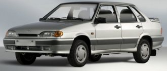
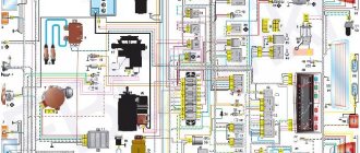
Electric sema VAZ 21102
| 1 — block headlight | 35 — instrument lighting switch |
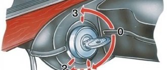
| 2 - front brake pad wear sensors | 36 - ignition switch |
| 3 - reverse light switch | 37 - mounting block |
| 4 — electric motor of the engine cooling system fan | 38 - recirculation valve switch |
| 5 - sound signal | 39 — heater controller |
| 6 — gear motor for locking the right front door lock | 40 - hazard warning switch |
| 7 - power window relay | 41 — lamp illuminating the heater control levers |
| 8 - 8 A fuse | 42 — glove box lighting lamp |
| 9 - starter | 43 - glove compartment light switch |
| 10 - accumulator battery | 44 - cigarette lighter |
| 11 - generator | 45 — display unit of the on-board control system |
| 12 - windshield washer motor | 46 - ashtray lighting lamp |
| 13 — washer fluid level sensor | 47 — brake light switch |
| 14 — gear motor for locking the left front door lock | 48 — gear motor for locking the left rear door lock |
| 15 - left front door power window switch | 49 - left rear door power window switch |
| 16 — coolant level sensor | 50 — electric window motor of the left rear door |
| 17 - windshield wiper motor | 51 — socket for a portable lamp |
| 18 - recirculation valve | 52 - watch |
| 19 — micromotor gearbox for heater damper drive | 53 — electric window motor gearbox of the right rear door |
| 20 — electric heater motor | 54 — right rear door power window switch |
| 21 — trunk lock switch | 55 — gear motor for locking the right rear door lock |
| 22 - right front door power window switch | 56 - side turn signal |
| 23 — electric window motor reducer of the right front door | 57 - parking brake warning lamp switch |
| 24 — control unit for the door lock system | 58 — driver's seat belt sensor |
| 25 — additional resistor for the heater motor | 59 - directional lamp |
| 26 — brake fluid level sensor | 60 - interior lamp |
| 27 — electric window motor reducer of the left front door | 61 — cabin air temperature sensor |
| 28 - outdoor lighting switch | 62 — switch in the front door pillar |
| 29 — instrument cluster | 63 — switch in the rear door pillar |
| 30 - rear fog light switch | 64 — external rear light |
| 31 — fog light indicator lamp | 65 - internal rear light |
| 32 — indicator lamp for heated rear window | 66 — license plate lights |
| 33 — rear window heating switch | 67 - trunk light |
| 34 - Understeering's shifter |
A
— blocks for connecting the rear window washer motor.
B
- blocks for connecting the injection system harness.
C
- to the warning light harness block.
D
— block for connection to the on-board computer.
E
- to the headlight cleaner harness block.
F
— block for connection to the fuel level sensor in the electric fuel pump module.
G
- to the rear window heating element.
H
- block for connecting an additional brake signal.
J
- to the trunk lock motor.
The diagram does not conventionally show that in the instrument panel wiring harness, the second ends of all wires of white, black, orange, white with a red stripe and yellow with a blue stripe are connected to each other at the same points.
Connection diagram of the engine management system 2111 with distributed fuel injection of the VAZ-21102 car
- 1 – injectors 2 – spark plugs 3 – ignition module 4 – diagnostic block 5 – controller (since 2000, a modification of the system with M1.5.4N or “January-5.1” controllers has been produced) 6 – cooling system fan electric motor 7 – block attached to instrument panel wiring harness 8 – main relay 9 – fuse connected to the main relay 10 – electric fan relay 11 – fuse connected to the electric fan relay 12 – electric fuel pump relay 13 – fuse connected to the electric fuel pump relay 14 – mass air flow sensor
- 15 – throttle position sensor
- 16 – coolant temperature sensor
- 17 – CO potentiometer (not installed on vehicles with a modified control system, CO adjustment is carried out using the DST-2 device through the diagnostic block)
- 18 – idle speed regulator
- 19 – knock sensor
- 20 – crankshaft position sensor
- 21 – vehicle speed sensor
- 22 – immobilizer control unit
- 23 – immobilizer status indicator
- 24 – electric fuel pump with fuel level sensor
- 25 – oil pressure warning lamp sensor
- 26 – coolant temperature indicator sensor
- 27 – oil level sensor
- 28 – knock sensor (installed on vehicles with a modified control system)
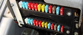
Fuse box VAZ-2110, VAZ-2111, VAZ-2112
F1 - 5A - License plate lamps. Instrument lighting lamps. Side light indicator lamp. Trunk light. Left side marker lamps. F2 - 7.5A - Left headlight (low beam). F3 - 10A - Left headlight (high beam). F4 - 10A - Right fog lamp. F5 - 30A - Electric door window motors. F6 - 15A - Portable lamp. F7 - 20A - Electric motor of the engine cooling system fan. Sound signal. F8 - 20A - Rear window heating element. Relay (contacts) for turning on the heated rear window. F9 - 20A - Recirculation valve. Windshield and headlight cleaners and washers. Relay (coil) for turning on the heated rear window. F10 - 20A - Reserve. F11 - 5A - Starboard side marker lamps. F12 - 7.5A - Right headlight (low beam). F13 - 10A - Right headlight (high beam). Indicator lamp for turning on the high beam. F14 - 10A - Left fog lamp. F15 - 20A - Electric seat heating. Locking the trunk lock. F16 - 10A - Relay-breaker for direction indicators and hazard warning lights (in emergency mode). Hazard warning lamp. F17 - 7.5A - Interior lighting lamp. Individual backlight lamp. Ignition switch illumination lamp. Brake light bulbs. Clock (trip computer). F18 - 25A - Glove box lighting lamp. Heater controller. Cigarette lighter. F19 - 10A - Door locking. Relay for monitoring the health of brake light lamps and side lights. Direction indicators with warning lamps. Reversing lamps. Generator excitation winding. On-board control system display unit. Instrument cluster. Clock (or trip computer). F20 - 7.5A - Rear fog lamps.
There are no fuses in the starting circuit.
Relay designation:
K1 – relay for monitoring the health of light bulbs; K2 – front wiper relay; K3 – repeater and alarm relay; K4 – low beam relay; K5 – high beam relay; K6 – additional relay; K7 – relay for turning on the heated rear window; K8 – backup relay (not installed on 110 series vehicles);
Basic and additional diagrams of the VAZ 2109 passenger car
This article contains a color general diagram of a VAZ 2109 passenger car. For a better understanding of how to connect individual electrical devices and circuits to the overall diagram, additional electrical diagrams of these devices are presented on this page. All electrical diagrams have explanations and explanations of the designation points. At the beginning of the article there is a table of modifications of the VAZ 2109 car produced by the Volga Automobile Plant for domestic and foreign markets. It supplements information about the electrical devices of this vehicle. For additional information about the design of electrical systems, equipment and circuits of the VAZ 2109 passenger car and its modifications, there is a section of special technical literature on this page. There you can view and download the necessary catalogs and manuals for the repair and operation of these vehicles.
Features of electrical equipment
Generator Differences
It was already mentioned earlier that the wiring diagram of the VAZ 21213 had some differences, primarily related to the installed power unit.
In particular, fuel-injected versions required a more powerful generator, so:
- A generator model 371.3701 was installed on the VAZ 21213;
- The VAZ 21214 was equipped with generator model 9412.3701.
They are structurally similar and are synchronous AC machines with a built-in rectifier and output voltage regulator.
Electric generator circuit for the carburetor version of the Niva car
Wiring Differences
The VAZ 21213 engine compartment wiring is made in different designs to facilitate do-it-yourself maintenance.
Niva wiring harness for installation in the engine compartment
For versions with an injection power unit, the wiring on the VAZ 21213 has three additional connectors for the contactless ignition unit.
In addition, the VAZ 21214 model has 2 radiator cooling fans, so the wiring for them also has its differences from the “thirteenth”. A schematic diagram of connecting the elements of the cooling system is presented below.
Electrical diagram for connecting Niva fans
How to read car electrical diagrams - basic symbols
In order to understand the principle of operation of a device, a knowledgeable person will only need to look at the electrical diagram. Let's look at the main nuances that will help even a beginner understand the circuits. It is clear that not a single device will operate without current, which is supplied through internal conductors. These routes are indicated by thin lines, and their color should match the actual color of the wires.
If the electrical circuit consists of a large number of elements, then the route on it is depicted with segments and breaks, and the places of their connections or connections must be indicated.
The numbers indicated on the nodes must correspond to real numbers. The numbers in the circles show the connections of the wires with a “minus”, and the designation of current-carrying paths makes it easier to find elements located on various circuits. Combinations of numbers and letters correspond to detachable connections. There are special tables that make it very easy to identify elements of electrical circuits. They are very easy to find both on the Internet and in manuals for specialists. In general, car electrical diagrams are quite easy to read; the main thing is to understand the functionality of their elements and follow the numbers.
When reading the electrical diagram, you should consider some features:
Source
What are car wiring diagrams?
What devices and elements does the vehicle's electrical wiring and electrical equipment system include? A schematic electrical diagram is a visual representation where all the icons of the components used are indicated without exception. All devices are located in a specific order on the diagram, and they can be connected to each other in either a serial or parallel manner. It must be taken into account that the electrical diagram of a car or truck itself does not actually show the actual location of the equipment. It only shows how all consumers and energy sources are connected.
Regardless of the machine, the circuit includes the following components:
Why understand electrical circuits?
Being able to read such diagrams is quite important for anyone who owns a car, because it will help save a lot of money on the services of a specialist. Of course, fixing any serious breakdowns on your own without the participation of professionals is difficult, and even fraught, because the current does not tolerate mistakes. However, if we are talking about some basic malfunction or you need to connect the battery, ECU, headlights, side lights, etc., then doing it yourself is quite possible.
In addition, we often want to add additional electronic devices into the circuit, such as an alarm system, a radio, or a car air conditioner, which greatly facilitate the driving process and fill our lives with comfort. And here you cannot do without the ability to understand electrical circuits, because they are often included with all of the listed devices. This is also relevant for owners of cars with a trailer, as sometimes problems arise with its connection. And then you will need a wiring diagram for a passenger car trailer and, naturally, the skills to understand it.
Standard elements of a car circuit diagram
Let us finally begin to examine the elements of the diagram and learn how to read it.
Standard power circuits and connection of elements
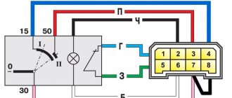
Power circuits - circuit elements that transmit current, are depicted by lines: at the top of the diagram there are circuits with a positive potential (“plus” of the battery), and at the bottom - with a zero potential, i.e. ground (or battery negative).
Circuit 30 - comes from the positive terminal of the battery, 15 - from the battery through the ignition switch - “Ignition 1” Circuit number 31 - grounding
Some wires also have a digital designation at the point of connection to the device; this digital designation allows you to determine where it comes from without tracing the circuit. These designations are combined in the DIN 72552 (frequently used values):
For convenience, connections between elements on color diagrams are depicted in different colors corresponding to the colors of the wires, and on some diagrams the wire cross-section is also indicated. On black and white diagrams, the colors of the connections are indicated by letters:
Sometimes you can find an empty circle in a node - this means that this connection depends on the configuration of the car, and the lines are usually signed.
Designation of connectors on the electrical diagram - connectors
Wires in car wiring are connected in several ways, and one of them is connectors. The connectors are designated by the letter “C” and a serial number. In the figure on the left you see a schematic representation of the connections of sections of wire through connectors. In general, it is more correct to say not “pin No. 2”, but “terminal No. 2”; if you come across such a concept in the diagram, then now you will know that this is the serial number of the connection (contact) in the connector.
What opportunities open up for a car owner who understands the circuits?
Every car owner should understand the auto electrical circuit, since if problems arise in the operation of the equipment, you can deal with the breakdown yourself. Naturally, if more complex problems occur in the operation of the network and equipment, then it is unlikely that you will be able to identify them yourself without experience. Especially when you consider that modern cars use more complex circuits, which is associated with the use of a larger number of various devices.
Also, the need to understand the operation of a particular circuit for a car may arise for those car owners who want to make adjustments to the operation of the system. For example, if you are planning to improve and tune your vehicle, this does not necessarily mean using upgraded body kits or bumpers. If the interior is being tuned, the car owner can install a new audio system or air conditioner, in which case it is impossible to do without making changes. In addition, you need to understand the operation of the circuit even if you decide to install an anti-theft installation yourself.
Those motorists who periodically use a trailer should also be able to understand the circuit, since our compatriots often face connection problems. One way or another, if you want to install additional devices and add their system, then understanding the electrical circuit is simply necessary.