Air purifier care
Rice. Carburetor air filter: 1 - valve; 2 — valve seat; 3 — sealing gasket; 4 - spring; 5 - glass; 6 — nylon packing; 7 — air cleaner housing; 8 — receiving pipe; 9 — crankcase ventilation tube; 10 — ventilation tube for the carburetor float chamber; 11 — pipe to the carburetor; 12 — spring latch; 13 — lock handle; 14 - pallet; 15 — swirler; 16 - oil deflector, A - purified air; B - unpurified air; B - oil.
To wash the filter packing, clean the pan 14 and change the oil in it, disconnect the filter housing from the engine, loosen the clamp on the outlet pipe and the lock clamp on the tension band. Disconnect the pan from the air cleaner housing 7; wash the packing with gasoline or kerosene and let it drain.
Pour out the contaminated oil from the pan and wash the pan with kerosene or gasoline.
Pour 0.2 liters of fresh oil used to lubricate the engine into the cleaned pan. Filled in this way (attach the tray with locks to the top of the air cleaner.
When installing the filter, pay attention to the reliability of the seal of the outlet pipe and the carburetor neck in order to avoid the intake of contaminated air.
Fuel pump care
Caring for the fuel pump involves periodically cleaning it from contamination, for which you need to remove its cover and strainer.
You should also monitor the tightness of the gas pipelines, their condition, the tightening of the gas pipeline clamps, the serviceability of the diaphragm and pump valves.
It is recommended to remove and disassemble the pump only after identifying the need to replace its parts.
When removing the pump, it is necessary to ensure that the gaskets are intact.
Rice. Fuel pump: 1 - cover; 2 - filter; 3 — intake valve seat plug; 4 - suction valve; 5 — upper body; 6 - upper cup of the diaphragm; 7—internal remote gasket; 8 - diaphragm; 9 — lower cup of the diaphragm; 10 — lever; 11 — lever spring; 12 — rod; 13 — lower body; 14 — balancer; 15 - eccentric; 16 — axis of the lever and balancer; 17 — filler lever; 18 — pump gasket; 19 — sealing and adjusting gasket; 20 — pump drive rod guide; 21 — rod; 22 — spacer; 23 — remote gasket; 24 — discharge valve seat plug; 25 — discharge valve
In case of replacement of gaskets, pump, spacer 22, guide 20 or rod 21, it is necessary to use adjusting shims 19 to ensure normal operation and performance of the fuel pump.
Before installing the pump, it is necessary to press the lever 17 of the filler until the useful stroke begins and measure the distance between the lever and the mating plane of the pump body. The amount of sinking should be within the range A—1.0—1.5 mm.
Then you should install guide 20 with rod 21, spacer 22 and spacers 18 and 19 on the studs of the timing gear cover and, having secured them, turn the crankshaft until the maximum protrusion of rod 11. In this case, the rod should be pressed against the pump drive cam.
The rod 21 should protrude above the spacer 22 with spacer 18 by 1.7-2.8 mm more than the filler lever 17 recesses when choosing free play. The size of the protruding rod is regulated by a set of shims 19. Example: the filler lever is recessed by A-1.5 mm.
Accordingly, the amount of protrusion of the rod should be: 1.5 mm+(1.7-2.8) mm 3.2-4.3 mm.
Spare parts catalog LuAZ 969M
- Body Body Body
- Floor hatch covers, floor mats and gear 1
- Window window
- Ventilation hatch and its drive 5
- Tailgate 1
- Tent 6
- Doors 7
- Front seats 4
- Installation of heating system 4
- Internal and external mirrors 7
- Hood, front trim 1
- Engine 28 Power unit
- Fuel tank 1
- Silencer 3
- Cooling fan 3
- Clutch 12 Clutch 2
- Gearbox housing 7
- Drive shaft and compensation couplings 4
- Half shafts 8
- Differential with installation details 3
- Frame, bumpers and engine mudguards 15 Engine compartment mudguards 3
- Front suspension installation 6
- Steering rods and pendulum arms 6
- Wheels and tires 1
- Steering control 22 Steering control (as of 03.81) 5
- Front and rear wheel brakes 3
- Electrical equipment 433 Generator 6
- Instrument panel, flexible speedometer shaft, temperature and oil pressure gauge sensors 23
- Tools and accessories 62 Tools and accessories 62
645ab32ed460089b8426929027d4deab
Carburetor care
Carburetor care involves checking the tightness of all connections, plugs and plugs, removing sediment from the float chamber, as well as periodically, at least twice a year, cleaning and flushing parts, jets and carburetor channels. It is recommended to flush the carburetor with gasoline, and in case of very strong contamination with resinous substances - with acetone. Washed parts; The jets and channels need to be blown out with a stream of compressed air. It is absolutely unacceptable to use wire, even soft wire, to clean jets.
Engine malfunction due to clogged carburetor jets and valves is extremely rare. However, if clogged, they should only be cleaned by blowing with compressed air.
Accelerator pump care
The need to check the operation of the accelerator pump arises when there are noticeable “failures” in the operation of the carburetor (delay in response to transient conditions). To check the pump, remove the float chamber cover, unscrew screw 4 of the accelerator pump, and, pressing the throttle lever, make sure that gasoline is supplied to the open hole. If gasoline is supplied, the valve and nozzle should be blown out and reinstalled. If gasoline does not flow, flush the chamber and ensure smooth operation of the accelerator pump piston.
The need to check the tightness of the fuel supply valve arises when there is an overflow of gasoline, gasoline leaking through the accelerator pump drive rod and in other places, or increased fuel consumption.
Rice. Float with fuel valve: 1 - float; 2 — tongue for setting the level; 3 — float travel limiter; 4 — float axis; 5 — fuel supply valve seat; 6 — float chamber cover; 7 — fuel supply valve needle; 8 - sealing washer
To check the tightness of the valve, it is necessary to remove the float chamber cover and check the tightness of the valve. If necessary, replace sealing washer 8 or the fuel valve assembly.
To avoid destruction of the sealing washer, the following is not allowed:
- a) wash the valve with acetone or other solvents;
- b) press float 1 on valve needle 7 when adjusting the fuel level in the float chamber.
When the valve is closed, the float must be positioned so that the longitudinal stampings on it are parallel to the plane of the connectors when the cover is inverted.
The position of the float is adjusted by bending the stop tongue 2, at the same time it is necessary to set the needle stroke of the fuel supply valve to 1.2-1.5 mm by bending the float stroke limiter 3.
Checking the gasoline level in the float chamber. After each disassembly and reassembly of the carburetor, as well as periodically during the operation of the car, check and, if necessary, set the gasoline level in the float chamber 21-23.5 mm below the plane of the connector between the body and the carburetor cover.
Rice. Checking the fuel level in the carburetor float chamber: 1 - scale ruler; 2 — glass tube; 3 - fitting; 4 - gasket; 5 - carburetor
The level of gasoline in the float chamber can be determined using a glass tube 2 with a diameter of at least 9 mm, connected by a rubber tube to a specially made fitting 3, which is screwed into the bottom of the float chamber instead of a drain plug.
To check the gasoline level, there is a convex mark on the wall of the float chamber housing.
After screwing the fitting into the hole closed by the drain plug, the glass tube is held in a vertical position, pressing it against the wall of the float chamber body, and gasoline is pumped into the carburetor using the manual pumping lever.
Using ruler 1, measure the distance from the upper plane of the float chamber to the fuel level in the float chamber (to the bottom of the meniscus).
After checking the level, you must install the drain plug.
Some features of repair work
If you have any malfunctions, you should fix them immediately. The work is not complicated, because there are no electronics in the system; we will consider only the most general recommendations, without delving into the process.
Maintenance
For work, you will need a simple set of tools and a tester, with which you can quickly and accurately diagnose the system and check the presence of current in a particular node.
In general, here are some tips:
- If the generator does not provide high-quality charging, it is best to replace it, and there can be many options - from VAZ units to foreign cars, the main thing is to choose the optimal configuration of the equipment so that you can get by with a minimum number of alterations, most often you need a bracket, the rest is adjusted locally.
If you are installing a more powerful generator, use this circuit
- When replacing individual cores, be sure to follow the color coding, otherwise it will be difficult to figure out what goes where. That is, if you change the red wire, then replace it with a new product of the same color. When the required option is not available, you can temporarily use what you have, but then be sure to replace it with the correct one.
This connection is not allowed
- Pay special attention to all connections, as they are the most common cause of malfunctions. Twists and electrical tape are unacceptable; you must purchase crimping pliers, install terminals on all ends of the wires, and cover the crimping area with heat-shrink tubing . In some cases, you can make a connection using a soldering iron, but after that it must be carefully tinned and covered with the same heat shrink.
Read more: Why the DVR won’t turn off
This is what a correctly assembled contact looks like
Replacing electrical wiring
If the LuAZ wiring is in a very poor condition, then it is easier to replace it completely than to work with individual components.
The following can be noted on this issue:
- Finding an original kit is often very difficult, so as a way out of the situation you can use a ready-made wiring kit from a VAZ 2106. It is ideal for doing the job; you just need to understand the diagram in order to understand where each node should be connected. The length of all the harnesses is quite sufficient, and the price of this option is quite affordable.
Underhood wiring hidden in corrugation
- When laying the system, it is best to secure the harnesses with plastic clamps; this ensures the highest reliability and durability of the connections, because plastic does not rot or rust. In addition, if necessary, it is easy to cut the clamps and then install new ones; their cost is just a penny, so you will not incur any extra costs.
- All connectors must be connected tightly and securely fixed, this eliminates loss of contact when moving when the structure is affected by vibration and shaking.
Caring for a gasoline sump
Maintenance of the gasoline sump (installed on the left side member under the floor of the car) consists of draining the water and sediment, as well as washing the filter element (set of plates), for which you need to unscrew the bolt on the sump cover and remove the housing along with the filter element. When disassembling the sump, it is important not to damage the gasket that ensures the seal of the housing. To drain the sediment from the filter, you need to unscrew the drain plug at the bottom of the housing, drain the sediment and rinse the filter with clean gasoline.
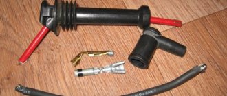
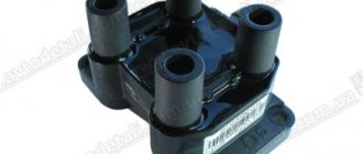
Ignition coil care
During operation, you must do the following:
- Avoid contamination of the plastic cover, terminals and wires; At each technical inspection, wipe the cover with a cloth - dry or moistened with clean gasoline.
- Do not loosen the fastening of the wires to the cover terminals.
- Protect the coil from mechanical damage; A crack in the cover or a dent in the casing can damage the coil.
At each technical inspection, clean the ventilation holes of the resistor located between the legs of the coil mounting clamp from dirt.
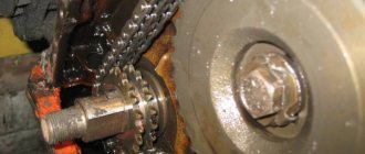
Caring for the ignition distributor
During operation, it is necessary to maintain the contacts of the distributor in good condition (keep them clean and check the size of the gap between them), monitor the lubrication of the rubbing parts and remember that it is forbidden to use oil from the engine crankcase to lubricate the distributor and that excessive lubrication of the distributor is harmful, since can lead to rapid wear of the breaker contacts and failure of the distributor.
It is necessary to ensure the cleanliness of the cover and distributor housing, as well as the contact of the wire tips in the cover terminals. If the contact is not reliable enough, the plastic of the cover burns out inside the terminal sockets, which leads to failure of the cover and spark plug tips.
When servicing the distributor, you should:
- Remove the distributor cap and thoroughly wipe it inside and out with a dry, clean cloth or a cloth soaked in gasoline. Inspect the cover and slider.
- Check the reliability of the connection of the low and high voltage wires.
- Check the fastening of the distributor vacuum regulator pipelines.
- Check if there is any jamming of the contact carbon - resistance in the lid.
- Turn the oiler cap 1-2 turns to supply lubricant to the distributor shaft. If the oiler cap is screwed in completely, unscrew it and fill it with CIATIM-201 or LITOL-24 lubricant. Lubricate the rubbing parts of the distributor with clean engine oil by placing: 1-2 drops on the axis of the contact lever, 4-5 drops in the cam bushing (removing the slider and the oil seal underneath), 1-2 drops on the cam fillet.
- Check the cleanliness of the breaker contacts and, if necessary, remove dirt and oil from them. Contacts should be wiped with chamois soaked in gasoline. Instead of suede, you can use any fabric that does not leave fibers on the contacts, and instead of gasoline, use alcohol. After grinding the contacts, you need to pull the breaker lever away from the fixed contact for a few seconds to allow the gasoline to evaporate.
- Check the condition of the working surface of the contacts and, if necessary, clean them. The contacts are cleaned with a special abrasive file or on an abrasive stone with fine grain, removing the lever and the stand with the fixed contact from the distributor. When cleaning the contacts, you need to remove the bump on one of them and somewhat smooth the surface of the other, on which a depression (crater) is formed. It is not recommended to remove this depression completely. After cleaning the contacts to remove dust, the breaker must be blown with dry compressed air, wipe the contacts with a dry, clean cloth (passing it between the contacts) and adjust the gap between them.
- Inspect the cam and, if it is dirty, wipe it with a dry, clean cloth and lubricate it with a thin layer of CIATIM-201 lubricant.
Features of wiring in this model
Let us note right away that in the production of the cars in question, economy has always been a priority, so you can find models with one drive axle (there were simply not enough of these units at one time) and other solutions that reduced the cost, but negatively affected the reliability and durability of the structure.
The following factors can be noted:
- Most cars were equipped with a generator without an integrated board; it did not differ in power, so when idling, most often the battery was not charged, which had a very negative impact on the operation of the battery and sometimes, especially in the cold season, the battery could simply run out.
This diagram is valid for all cars manufactured from March 1981 to August 1986, equipped with a generator without an integrated board
- But generators with an integrated circuit worked much better; they were distinguished by better charging and stable operation of the design. The wiring diagram is similar to the one above, the only difference is in the generator unit. You can easily see the difference yourself by comparing the diagrams in the photo; the generator is indicated by the number 8.
Read more: Replacing the w211 fuel filter
An improved version of the generator caused changes in the circuit
Advice! Some car owners include more powerful generators in this scheme; this provides brighter light and stable battery charging at any speed.
- The wires themselves are not reliable and over time they begin to burn out, rot, or the insulation simply dries out and collapses. There are some simple tips on how to extend the life of the system with your own hands, but this will require time and effort - you need to lay all the harnesses in special corrugations and protect all contacts by installing high-quality terminals and protecting them with heat-shrinkable tubing.
- The electrical wiring of the LuAZ requires constant inspection in order to identify faults at the stage of their development, since if you get stuck in the middle of off-road conditions, the work will become much more complicated.
- In the nineties, cars began to be equipped with ignition switches without steering column locking , which again caused a change in the circuit, but this is not so fundamental. In general, it can be noted that the design has remained virtually unchanged, therefore, having understood one modification, you can easily understand all the others.
- In order to better understand which electricity consumers are included in the system, look at the circuit diagram below. This is a kind of instruction that will help you understand how the circuit works and what is included in it.
From this picture it is easy to understand the features of LuAZ electrical equipment
Adjusting the gap between the breaker contacts
To ensure normal operation of the ignition system, the gap between the contacts of the breaker must be adjusted within 0.35-0.45 mm or, when diagnosing the engine, the angle of the closed contact is 54-62° along the distributor shaft.
The gap is adjusted as follows. It is necessary to remove the distributor cover 1 and the slider 2 and slowly turn the engine crankshaft with the starting handle to a position where the gap between the contacts 3 of the breaker is greatest, i.e. when the textolite cam 4 of the breaker is installed on the top of the edge of the cam 5. After this, check the gap with a flat feeler gauge between contacts. If the gap does not correspond to the value indicated above, it is necessary to loosen screw 17 and, turning the eccentric 6, set the required gap, then fasten the screw and check the gap again. Then you need to put the cover in place and secure it with latches 8. After adjusting the gap between the breaker contacts, the correct setting of the ignition timing is disrupted. Therefore, the ignition installation must be checked and, if necessary, adjusted.
Conclusion
Understanding the wiring of the LuAZ 969 is many times easier than in any modern model, because there are no electronics, control units or other complex components. The video will help you understand the issue even better and clearly show some important features.
Dear visitors, dear friends, hello everyone.
In this topic, I want to share with you one trip in a Luaz 969 m car in which I took part. The car's cross-country ability is good; the car is still characterized by many motorists as an excellent means of transportation in adverse weather conditions. Luaz 969 m was produced by the Lutsk Automobile Plant in the 80s of the last century. There are various modifications for this vehicle in operational use. Also, car enthusiasts are upgrading the ignition system itself, from a contact (for battery ignition) to a contactless ignition system. A person’s imagination is limitless in modernization, but I believe that the car, as Luaz was, will remain so with any modernization. If we install an engine from a VAZ, the speed of the Luaz 969 m car will increase accordingly, but in the future, this may affect the parts of the car’s chassis. But that's just my opinion.
The trip out of town that I want to tell you about was as follows:
We went not far out of town just to relax, the owner of the car was a friend of mine. Upon arrival in the village to visit friends, a few meters short of driving, the car stalled; it was evening. It stalled, well, okay, the main thing is we got to the place. The next day, the three of us began to look for the cause of the car malfunction; the starter was turning - Luaz would not start. We were not a high level of specialists in the electrical part of the car, especially after a good rest. It was unknown to us where to look for the cause of the malfunction.
Read more: Land of spare parts at the catcher's
Ignition installation
Rice. Ignition distributor: 1 — cover; 2 — slider (distributor rotor); 3 — breaker contacts; 4—moving contact cam; 5 - cam; 6 — eccentric screw, 7 — low voltage terminal; c" latch; 9 — felt brush for lubrication of the cam; 10 — adjustment lever; 11 — nut of the bolt securing the octane corrector plate; 12 — movable octane corrector plate; 13 — bolt of the clamp of the movable plate of the octane corrector; 14 — fixed octane corrector plate; 15 — nut for fastening the fixed plate of the octane corrector; 16 — cap oiler; 17 — locking screw
Ignition is set according to the MZ mark, indicating the ignition timing in the first cylinder. The opening of the breaker contacts should begin at the moment when the M3 mark on the oil purifier cover coincides with the mounting lug a on the timing gear cover. In this case, slider 2 (distributor rotor) must be located against the distributor electrode with number 1. The order of operations when installing the ignition is as follows:
- Remove the distributor cap and rotor, check the gap between the breaker contacts (adjust if necessary). Put the rotor in place.
- Set the crankshaft to the position corresponding to the beginning of the compression stroke in the first cylinder.
- Slowly turn the engine crankshaft until the M3 mark coincides with the protrusion on the camshaft cover. Make sure that the rotor is against the contact of the cover connected to the wire going to the spark plug of the first cylinder.
- Loosen nut 11, set the octane corrector to the zero scale division by turning adjusting lever 10, tighten nut 11 of the bolt securing the octane corrector plates.
- Loosen the tightening of bolt 18 of the clamp securing the distributor housing to the movable plate 14 of the octane corrector and turn the housing counterclockwise so that the breaker contacts close.
- Take a portable lamp and two insulated wires. Using additional wires, connect one end of the portable lamp plug pin to ground, and the other to the low voltage terminal of the ignition coil, to which the wire going to terminal 7 of the distributor is attached.
- Turn on the ignition and carefully turn the distributor housing clockwise until the lamp lights up.
- Stop the rotation of the distributor exactly at the moment the light flashes. If this fails, repeat the operation.
- While holding the distributor body from turning, tighten bolt 13 of the body mounting clamp, and put cover 1 in place.
- Check the connection of the wires from the spark plugs, starting from the first cylinder, in the order 1-3-4-2, counting them counterclockwise. It should be borne in mind that setting the ignition to the M3 mark on the pulley with the octane corrector in the middle position provides the most favorable power and economic performance of the engine only if the appropriate gasoline is used to power it.
- However, after each installation of the ignition, adjustment of contacts in the breaker, or replacement of fuel, it is necessary to check the compliance of the ignition timing while the vehicle is moving. The final installation of the ignition is performed using an octane corrector. Warm up the engine at idle speed, and then, moving in fourth gear on a flat road at a speed of 25-30 km/h, accelerate the car by sharply pressing the throttle pedal. If a slight and short-term detonation is observed, then the ignition is considered to be installed correctly.
In case of strong detonation, the “arrow” of the movable plate should be moved towards the “-” sign to reduce the ignition timing, and in the complete absence of detonation - towards the “+” sign.
The largest ignition advance (or retardation) angle, provided by manual adjustment using an octane corrector, is 12° (according to the angle of rotation of the engine crankshaft) relative to the initial setting (5° BTDC).
The engine is very sensitive to the correct setting of the ignition timing; ignition too early or too late leads to engine overheating, loss of power, burnout of valves and pistons.
LuAZ 969 Revival of the Legend › Logbook › Bought electronic ignition)
In general, I’m tired of the eternal problem of contact ignition, even with a new distributor, after a couple of days failures began again, everything is new! Therefore, I was categorically against contact ignition. And finally I bought an electronic one, I can’t wait to install it)))
And so, all I have to do is install all this, and I have a question for those who have already installed it, what needs to be removed from the original distributor?) Or just the holder itself? And leave the rest alone)
Spark plug care
During each vehicle maintenance, you must remove the spark plugs and do the following:
- Check the condition of the outer and inner parts of the insulator. If there is carbon deposits on the inside (skirt) of the insulator, you need to clean the insulator with a brush or sandblaster. After cleaning the carbon deposits, the spark plugs must be washed in gasoline. It is prohibited to clean carbon deposits from candles with sharp metal objects or to burn candles in an open flame, as this may damage the insulator. If carbon deposits are not removed, the spark plug must be replaced.
- Check the gap between the electrodes and, if necessary, adjust it, carefully bending only the side electrode. The gap is 0.6-0.75 mm checked with a round wire feeler gauge. Before unscrewing the spark plugs, you must thoroughly wipe the spark plug socket in the cylinder head from dirt to prevent dirt from getting into the engine. It is advisable to blow out the spark plug sockets with compressed air.
- The spark plugs should be unscrewed and tightened using a special socket wrench included in the driver's tool kit. It is prohibited to use other keys, as this may damage the insulator.
- You must first screw in the spark plug by hand until it stops, and then tighten it tightly with a wrench with a tightening torque of 35–40 Nm (3.5–4 kgfm). Place a sealing gasket under the spark plug. The absence of a gasket or loose screwing of the spark plug leads to overheating and failure of the spark plug.
- It is prohibited to replace A23-1 spark plugs with others with a lower heat rating. Inconsistency in the thermal characteristics of spark plugs leads to unsatisfactory engine performance, burnout of pistons and exhaust valves.
source
Electronic ignition for LuAZ
Product available in our warehouse!
Were you looking for spare parts for LuAZ, ZAZ Zaporozhets, AZLK Moskvich? Congratulations, you found them! You don't have to look any further