Troubleshooting the unit
Upon completion of diagnostic operations on the VAZ 2107 engine, other breakdowns that may have similar manifestations should be excluded. The econometer works by changing the pressure in the carburetor channels; damage to its tube can lead to air leaks. A modern injector electronic control system eliminates electro-pneumatic devices that are less reliable.
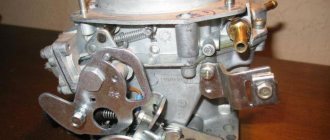
An accurate determination of the cause of the EPHH malfunction is only possible if the unit is dismantled and completely disassembled. The economizer is removed from the carburetor in the following order:
The operation scheme of the carburetor, which was replaced by an injector, assumes a reaction to changes in pressure in the chamber with a decrease or increase in fuel supply. The economizer implements this feedback through a flexible membrane rigidly connected to the stem and valve. When checking this block, special attention should be paid to this node.
There are repair kits for sale for Solex carburetors that were previously installed on the VAZ 2107. The forced idle unit, if it does not work, can be repaired using parts from such a kit. Installation of the unit in its intended place must be accompanied by a leak test. The last thing to connect before installing the air filter is the econometer located on the control panel. The position of the arrow in the green sector indicates acceptable fuel consumption.
A VAZ 2107 car with a gasoline engine is equipped mainly with an Ozone carburetor; it controls idle speed using an electric pneumatic valve. This valve shuts off the fuel supply when the ignition is turned off.
Cars of this model were not equipped with engines that use a more modern 16-valve timing system. The pneumatic valve of a car with a carburetor is highly reliable in comparison with other models. This device allows you to avoid glow ignition in the cylinders after stopping the engine, and also save fuel. The principle of operation of the electro-pneumatic valve is that it shuts off the fuel supply through the idle channel. This design is much simpler than previously used EPPCs. After minor improvements, this valve began to be used in power supply systems for engines equipped with a 16-valve gas distribution mechanism. They were used on them until the installation of distributed and mono injection.
Car fuel economizer myth or reality
September 14, 2021 Stay informed
Currently, you can find car fuel economizers for sale in auto parts stores. Let's figure out why it is needed and whether it is useful.
Due to the constant rise in fuel prices, the problem of saving fuel becomes extremely urgent.
The retail price of gasoline and diesel fuel does not decrease even if the price of oil falls,
Of course, you can try more radical methods such as installing gas equipment. But it costs a lot of money, although it pays off over time. And I want to feel the fuel savings now. Putting your car in a parking lot or garage until better times comes is also not an option. After all, for many this is the only way to get to work.
The solution may be to use additional economizer accessories. They allow you to reduce fuel consumption and are so generously praised by their manufacturers. But are these strange devices actually capable of reducing gas mileage? Or is this just another marketing ploy?
Does an economizer help save fuel?
The most daring manufacturers claim fuel savings of up to 30%. According to them, the effectiveness of economizers is based on their increase in spark power. This can help fuel burn more efficiently.
As you know, the power of a spark is determined by a number of factors. They differ in the characteristics of the car's electrical circuit and the characteristics of energy consumption by additional equipment. In addition, the conditions in which the vehicle is operated, including climatic and weather conditions. Fuel economizers are designed to optimize the performance of a car's engine. At the same time, improving engine response, increasing smoothness, reducing fuel consumption.
What is a car fuel economizer?
The economizer itself is a capacitor connected to the car's electrical system. It works on the principle of an additional battery, increasing the efficiency of the car's electrical system. When the motor is running, the capacitor is charged so that it can then release the accumulated electricity when necessary.
We recommend reading How to prevent tick bites in nature and in the city
It compensates for the voltage consumed by the equipment, ensuring efficient combustion of fuel and reducing the load on the battery and generator. This releases the energy required for the spark plugs to operate, which promotes efficient combustion of gasoline. All this together should increase the power of the car and the service life of its components. It may be possible to improve the environmental friendliness of the vehicle and save fuel.
But, despite the tempting promises of manufacturers, people who have at least a slight understanding of the operating features of a car understand that the effectiveness of such a device is practically zero. Evidence of this is the many negative reviews from motorists who bought into the promises. In addition, the so-called economizer not only does not save battery power, but, on the contrary, gradually discharges the battery. This creates additional problems for motorists.
As you can see, fuel economizers are a useless trinket that doesn’t deliver even a fraction of its promises. If such technologies worked, auto manufacturers would have long ago used them to attract customers with lower fuel consumption.
Tags: car fuel economizer
Luxury car for everyday driving
Previous post
Which car seat to choose for a child in the car
Next entry
Diagnosis of idle speed faults
In the carburetor of a VAZ 2107 car, the pneumatic valve is controlled by an electromagnet - solenoid. When current is applied, the valve opens and the mixture is supplied to the cylinders through a special channel, which ensures stable engine operation at idle. The electro-pneumatic valve is quite reliable, the main reasons when it can fail are:
All these malfunctions can be diagnosed by external characteristic signs. The engine continues to run after the ignition is turned off (glow ignition), this indicates that the electro-pneumatic valve has failed. This usually happens if the valve does not close completely. There may be various reasons for this, a blockage in the passage hole, a weakened spring.
Types of IAC
Self-adjustment of the carburetor on a VAZ-2107 car
Externally, the regulator somewhat resembles an electric motor with a conical needle in its design.
There are 3 types of such controllers.
- Solenoid. The regulators are the simplest in design. When voltage is applied, the internal core on the winding is triggered and placed in a specially provided slot, which makes it possible to reduce the diameter of the passage channel. This reduces the volume of air or fuel supplied. The simple design helps reduce the cost of the product. Such a regulator can only operate in the fully open and closed position.
- Stepper. These IACs consist of a winding and a special ring magnet. There are four windings in total. Control signals from the computer are supplied to one of the windings, which contributes to the rotation of the rotor. Because of this, the cross-section of the passage channel smoothly changes from the state of complete opening to complete closure, and vice versa.
- Rotary. Their operating principle is similar to solenoid IACs. But here the tasks of the core are performed by the rotor. The latter is capable of rotating in different directions, thereby changing the dimensions of the channel cross-section.
Depending on the type of motor and its technical factory characteristics, different types of regulators are used.
Restoring stable idle
Restoring a stable idle shouldn't be too difficult. Troubleshooting procedure;
If, however, the cause of the unstable idle speed has not been eliminated, you need to check the power supply control circuit. If the power supply circuit is broken, the carburetor pneumatic valve is constantly in the closed position. This results in the engine not idling. Repairing the open circuit will solve this problem without much effort.
Malfunctions associated with the electro-pneumatic valve are extremely rare, but if this happens, it should be replaced.
Vacuum from the intake manifold is supplied through the pneumatic valve to the economizer diaphragm, due to which the economizer needle valve opens
When the pneumatic valve is turned off, the economizer cavity above the diaphragm communicates with the atmosphere - the needle valve closes, interrupting the supply of the fuel mixture through the idle channel to the engine.
The microswitch supplies voltage to the air valve, bypassing the control unit, when the throttle valve is open.
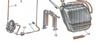
Diagram of the forced idle economizer system (EFS): 1 - solenoid pneumatic valve; 2 — intake manifold; 3 — economizer needle; 4 — economizer body; 5 — adjusting screw for the amount of mixture; 6 - microswitch; 7 — mounting block; 8 — ignition switch; 9 — ignition coil; 10 - control unit.
How to drive as economically as possible?
Fuel consumption is affected not only by the technical condition of the car, but also by driving style. Frequent and sharp accelerations and driving at high speeds lead to senseless excess fuel consumption. Correctly selected gear and a calm driving style reduces fuel consumption. But driving at low speeds does not always lead to a decrease in fuel consumption. How to achieve minimum fuel consumption?
In Europe, there is a developed movement (or sport?) “hypermiling”, where enthusiastic people set records for efficiency, but sometimes this desire reaches the point of absurdity, such as abandoning such things as air conditioning, making some unimaginable body kits for better aerodynamics, reducing weight , replacing all lamps with LEDs to reduce the load on the generator, etc. We will not go to such extremes for now.
On carburetor VAZs there was a mechanical economizer on the instrument panel. A device that allows you to estimate the load on the engine and, accordingly, instantaneous fuel consumption.
By keeping the needle in the green zone, it was possible to achieve minimal fuel consumption. The device operated due to a vacuum in the intake manifold after the throttle valve. The higher the load, the more the damper is open and the lower the vacuum, the further the needle deviates into the red zone.
Many modern cars (for example, Ford Focus 2 in the first photo and in the video) have a similar option, but it is inconvenient to use. The readings in numbers constantly jump and when we stand it shows consumption in liters per hour, when we start driving it switches to liters per 100 km. This doesn't suit me.
On the well-known hypermiler forum “ecomodder.com” they sell the “Scan Gaude 2” device, which is essentially an on-board computer with advanced functions for economical driving.
However, its price is very high, the set of functions is redundant, the size is huge and, again, the readings are in numbers, and this is inconvenient.
That’s why an electronic analogue of the VAZ economizer was made, only here we measure not the vacuum in the intake, but the duration of opening of the injectors over a certain time. And the amount of fuel poured into the engine over a certain time is directly displayed, this amount is displayed in the form of a progress bar. The meaning is the same, we are trying to reduce the amount of fuel poured in by changing our driving style, which is how we achieve a reduction in fuel consumption.
In the video, the operation of an electronic economizer on a Ford Focus 2, 1.6 engine, manual. As an example, to demonstrate why driving at low speeds is not always economical, I fully pressed the gas in high gear (0:56), as we can see, the amount of fuel increased sharply, but there was practically no acceleration, this is the wrong gear, such driving leads to to engine overload and increased fuel consumption.
In the near future, we plan to check what minimum consumption can be obtained during normal (not like a pensioner, but not like on a race track) driving on the highway.
Here are the English hypermilers' successes for 2021 - the Ford Fiesta, powered by the Engine of the Year award-winning 1.0L 123PS EcoBoost petrol engine, driven by former Ford factory rally team drivers Andy Dawson and Andrew Marriott. Andrew Marriott), demonstrated an average consumption of 2.9 liters per 100 km and won the category for cars with gasoline engines. The crew managed to improve the previous record by 14% and exceed the official fuel consumption data by 33%.
Features of our economizer:
- small size 4 x 1.5 cm
- does not require configuration
- easy connection
- suitable for injection cars
The economizer has three wires for connection, a white or green display color, and different options for the initial screen saver. Price 1000. Delivery by Russian Post First Class RUR 200.
For questions regarding the economizer, please contact +7 960 949 4825 or write to WhatsApp.
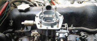
Checking and repairing the EPH system of carburetor 2105, 2107 Ozone
On some modifications of the 2105 - 2107 Ozone carburetor, a forced idle economizer system (EFS) is installed.
These are carburetors DAAZ 2105-1107010 Ozone and DAAZ 2107-1107010 Ozone. On the page “EPCH carburetors Ozone 2105, 2107” the design and principle of operation of the EPCH system is discussed. Here we will dwell in more detail on its malfunctions, inspection and repair.
Economizer check
1. If the economizer malfunctions, in some cases the engine may not idle at all or may operate unstably and intermittently. This may occur due to a leak in the economizer diaphragm or the tube supplying vacuum to it.
We remove the vacuum supply tube to the pneumatic valve and, bypassing the pneumatic valve, connect the fitting on the intake manifold and the economizer fitting. We start the engine, if it runs stably, then everything is fine, if not, then we change the economizer or the leaky vacuum supply tube.
2. In some cases, the valve needle gets stuck open and this leads to increased fuel consumption. With the engine running, remove one of the wires from the pneumatic valve, the engine should stall. If it does not stall, the needle may be stuck.
It is necessary to disassemble the economizer housing and eliminate needle jamming. To repair the economizer, use a Phillips screwdriver to unscrew the two screws securing the microswitch bracket and remove it. Next, we take out the economizer housing and, using the same screwdriver, disassemble it by unscrewing two screws.
We check the needle hang and the diaphragm. If the diaphragm is damaged, replace the economizer.
After repairing the economizer, it is necessary to adjust the carburetor idle speed. “Adjusting the idle speed of the Ozone carburetor”
Checking the microswitch (micro switch)
1. The throttle valves are closed, the choke valve is fully open, and the microswitch contacts are open. We connect a multimeter in ohmmeter mode to the microswitch terminals. Resistance should tend to infinity. If this does not happen, adjust the microswitch so that its contacts are open and test again. If nothing changes, replace the microswitch.
2. Turn the throttle valve drive lever, the microswitch contacts should close, and the multimeter should show resistance tending to zero. Otherwise it is faulty.
Initial position: the throttle valve is closed, the microswitch lever is pressed - the microswitch is turned off
Checking the pneumatic valve
1. Turn off the ignition. Through a rubber tube placed on one of the fittings of the pneumatic valve, we create a vacuum with our mouth (we draw in air). If the pneumatic valve is working properly, then air should not pass through it.
2. Turn on the ignition. The pneumatic valve must open and in this case air must flow through it. We try to remove and put on the plug of one of the wires suitable for the pneumatic valve from any of its terminals; a click should be heard when the pneumatic valve is activated. If this does not happen, change the valve.
Checking the pneumatic valve control unit
1. Connect the tachometer, if there is one built into the panel, then that will do.
2. Disconnect the wires from the carburetor microswitch.
3. Connect a voltmeter or multimeter in voltmeter mode. One wire is to ground, and the other is to the gray wire with a red stripe in the control unit block.
4. Start the engine.
5. The voltage on the voltmeter should be at least 10 V at idle. In this case, the pneumatic valve will be open.
6. We increase the speed to 1600 rpm, the voltage should drop to 0.5 - 1.5 V. The pneumatic valve closes.
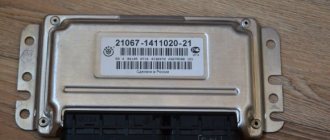
If, as a result of the adjustment, deviations in the operation of the control unit are revealed, then we replace it with a serviceable one.
7. Reduce the speed to 1200 rpm, the voltage should increase to 10 V. The pneumatic valve should open.
The control unit must turn off the pneumatic valve at a crankshaft speed of 1600 rpm and turn it back on at a speed of 1200 rpm.
If, as a result of the check, deviations in the operation of the control unit are revealed, then we replace it with a new one.
Notes and additions
Source
Russia Cars
Diagram of the carburetor solenoid valve control system
1 – ignition switch; 2 – ignition coil; 3 – control unit; 4 – solenoid valve; 5 – sensor-screw EPHH; A – to power supplies
Checking the carburetor solenoid valve control unit is shown on the engine mod. 2110.
PERFORMANCE ORDER 1. Start the engine and leave it idling. 2. Disconnect the connector of the EPHH sensor-screw wire and short-circuit the contact of the connector to ground (you can, without disconnecting the connectors, short-circuit the terminal of the carburetor sensor-screw to ground). 3. Smoothly opening the throttle valve, increase the crankshaft speed above 2100 rpm and fix this position. In this case, a self-oscillating mode of engine operation should occur, accompanied by a pulsation of the rotation speed.
The occurrence of a self-oscillating mode is explained by the fact that when the rotation speed increases to 2100 rpm, the electrical connection between terminals 4 and 6 (Fig. 7.20) of the unit is broken, which causes the fuel supply to the engine to be cut off. In this case, the rotation speed decreases and after it drops below 1900 rpm, the indicated relationship is restored, i.e., the fuel supply is resumed and the rotation speed increases.
This process is repeated cyclically with a period of 1–2 s.
If it is not possible to initiate the self-oscillating mode, and the solenoid valve is not defective (for checking the valve, see subsection 2.17.2.9, paragraph 67), then the control unit is faulty and must be replaced. 4. You can check the control unit by directly monitoring the rotation speed at which the unit operates using a tachometer.
To check, a 12 V test lamp and wires with plug tips are required.
Disconnect the block with wire from the solenoid valve output. To ensure the operation of the solenoid valve, connect its output with an additional wire to the “+” terminal of the battery. Connect one terminal of the control lamp to the contact of the block removed from the solenoid valve, and connect the other terminal of the lamp to the ground of the vehicle.
At idle speed (850±50) min–1, the control lamp should light up. When the rotation speed increases to 2100 min–1±5%, the lamp should go out and light up again when the rotation speed drops below 1900 min–1±5%.
After checking, connect the block with the wire to the solenoid valve terminal.
5. Loosen the ten bolts securing the head of the unit in the order shown, then completely unscrew the bolts securing the head and remove them along with the washers. 6. Slightly lift the cylinder head, slide it so that the end of the camshaft comes out of the hole in the rear drive belt cover, and remove the head.
COOLANT The frost resistance of the coolant depends on the ratio of water and TOSOL-A antifreeze in the solution, which can be determined by the density of the solution. New KamAZ vehicles are filled with coolant...
Checking and adjusting the parking brake GENERAL INFORMATION Frequency Every 30,000 km, check and, if necessary, adjust the parking brake. According to the Road Traffic Regulations, the parking brake must be held...
Generator - Checking and replacing the brush holder and capacitor GENERAL INFORMATION The generator is equipped with a K73-58-4 type capacitor. The marking is located on the side of the capacitor body. Do not install any other type of capacitor. EXECUTION ORDER 1. Disconnect...
Diagnosis of idle speed faults
In the carburetor of a VAZ 2107 car, the pneumatic valve is controlled by an electromagnet - solenoid. When current is applied, the valve opens and the mixture is supplied to the cylinders through a special channel, which ensures stable engine operation at idle. The electro-pneumatic valve is quite reliable, the main reasons when it can fail are:
All these malfunctions can be diagnosed by external characteristic signs. The engine continues to run after the ignition is turned off (glow ignition), this indicates that the electro-pneumatic valve has failed. This usually happens if the valve does not close completely. There may be various reasons for this, a blockage in the passage hole, a weakened spring.
Pneumatic valve control system for carburetor VAZ 2105 Zhiguli
9.13.1 Carburetor pneumatic valve control system Diagram of the carburetor pneumatic valve control system of the “Ozone” type 1 – microswitch in the carburetor; 2 – electro-pneumatic valve; 3 – mounting block; 4 – ignition relay; 5 – ignition switch; 6 – control unit for electro-pneumatic valve; 7 – ignition coil; A – to terminal “30”... 9.13.2 Checking the functionality of the control unit 25.3761 Diagram of the control system for the pneumatic valve of the Ozone carburetor 1 – microswitch in the carburetor; 2 – electro-pneumatic valve; 3 – mounting block; 4 – ignition relay; 5 – ignition switch; 6 – control unit for electro-pneumatic valve; 7 – ignition coil; A – to conclusion “30”...
9.13.3 Checking the solenoid valve control unit Addresses of the output terminals of the solenoid valve control unit Terminal Address 1 To the ignition coil terminal 2 Ground 3 – 4 +12 V from terminal “15” of the ignition switch 5 Carburetor limit switch 6 Solenoid valve to...
↓ Comments ↓
1. Vehicle operation
1.0 Vehicle operation 1.1. Starting the engine 1.2 Controlling the gearbox 1.3 Driving the vehicle 1.4 Braking and parking 1.5 Operating a new vehicle 1.6 Adjusting the ignition timing 1.7 Precautions when operating the vehicle 1.8 Caring for the body 1.9 Storing the vehicle
2. Car maintenance
2.0 Vehicle maintenance 2.1 Maintenance operations
3.0 General data 3.1 Technical characteristics of vehicles 3.2. Controls 3.3. Control of interior ventilation and heating 3.4 Tightening torques for threaded connections 3.5 Tools for repair and maintenance 3.6 Used fuels, lubricants and operating fluids 3.7 Basic data for adjustments and monitoring
4.0 Engine 4.1 Possible malfunctions, their causes and methods of elimination 4.2 Removing and installing the engine 4.3 Disassembling the engine 4.4 Assembling the engine 4.5 Bench tests of the engine 4.6 Checking the engine on the car 4.7. Cylinder block 4.8. Pistons and connecting rods 4.9. Crankshaft and flywheel 4.10. Cylinder head and valve mechanism 4.11. Camshaft and its drive 4.12. Cooling system 4.13. Lubrication system 4.14. Power system 4.15. Carburetor 2105-1107010 4.16. Carburetor 21051-1107010
5.0 Transmission 5.1. Clutch 5.2. Gearbox 5.3. Cardan transmission 5.4. Rear axle
6.0 Chassis 6.1. Front suspension 6.2. Rear suspension 6.3. Shock absorbers
7. Steering
7.0 Steering 7.1 Possible malfunctions, their causes and methods of elimination 7.2. Inspection, check and adjustment of the steering 7.3. Steering gear 7.4 Steering gear rods and ball joints 7.5 Bracket for pendulum arm
8.0 Brakes 8.1 Possible malfunctions, their causes and methods of elimination 8.2. Checking and adjusting the brakes 8.3 Clutch and brake pedal bracket 8.4 Vacuum booster 8.5. Main cylinder 8.6. Front brakes 8.7. Rear brakes 8.8. Rear brake pressure regulator 8.9. Parking brake
9.0 Electrical equipment 9.1 Possible malfunctions, their causes and methods of elimination 9.2 Circuits protected by fuses 9.3. Battery 9.4. Generator 9.5. Starter 9.6. Ignition system 9.7. Lighting and light signaling 9.8. Sound signals 9.9. Windshield cleaner 9.11. Heater fan electric motor 9.12. Control devices 9.13. Carburetor pneumatic valve control system
10.0 Body 10.1 Possible malfunctions, their causes and methods of elimination 10.2. Doors 10.3. Hood, trunk lid, bumpers 10.4. Body glazing, windshield and headlight glass washers 10.5 Instrument panel 10.6. Seats 10.7. Heater 10.8. Body frame repair 10.9. Paint coatings 10.10. Body anti-corrosion protection
11. Car modifications
11.0 Vehicle modifications 11.1. Features of repair of VAZ-21051 and VAZ-21053 cars 11.2. Features of repair of VAZ-2104 and VAZ-21043 cars 11.3 VAZ-21044 cars with a fuel injection system 11.4. Central fuel injection system design
12.0 Electrical diagrams 12.1 Interactive electrical diagram of the VAZ-2105 car 12.2 Electrical diagram of the VAZ-2104 car 12.3 Electrical connection diagram of the injection system 12.4 Connection diagram of the instrument cluster 12.5 Connection diagram of the brake system warning lamps 12.6 Connection diagram of the headlight cleaners and washers 12.7 Connection diagram of the heater fan motor 12.8 Diagram inclusion windshield cleaner and washer 12.9 Diagram for switching on direction indicators and hazard warning lights
Restoring stable idle
Restoring a stable idle shouldn't be too difficult. Troubleshooting procedure;
If, however, the cause of the unstable idle speed has not been eliminated, you need to check the power supply control circuit. If the power supply circuit is broken, the carburetor pneumatic valve is constantly in the closed position. This results in the engine not idling. Repairing the open circuit will solve this problem without much effort.
Malfunctions associated with the electro-pneumatic valve are extremely rare, but if this happens, it should be replaced.
Vacuum from the intake manifold is supplied through the pneumatic valve to the economizer diaphragm, due to which the economizer needle valve opens
When the pneumatic valve is turned off, the economizer cavity above the diaphragm communicates with the atmosphere - the needle valve closes, interrupting the supply of the fuel mixture through the idle channel to the engine.
Operating principle
To determine the cause of the problem and take action to troubleshoot the EPHH, you need to know about the principle of its operation.
Article on the topic: The heater damper does not work on the VAZ 2110: reasons and self-repair
If the car is coasting with the gear engaged and the accelerator pedal released, the EPHH will not turn on, even if the revolutions drop below 1900 per minute. The economizer monitors the closed position of the damper. If the engine speed at idle is too high, it is perceived as coasting.
Actually, this is all you need to know about the operation of such an element as EPHH.
Practice and research show that the use of an economizer allows you to save about 5 percent of engine consumption.
Device
The VAZ 2109 carburetor consists of two main elements - the body and the cover. All parts are mainly located in the housing (pump, jets, float, etc.). Also, the power system, which may be associated with repairs, includes: candles, EPHH, and so on.
When the pump pumps fuel from the tank, it first enters the carburetor float chamber block. This chamber is also called the first or primary. It serves to maintain an optimal level of gasoline at which the carburetor can operate normally and maintain stable speed. At the entrance to the chamber, there is a special fitting through which fuel passes. Its quantity is controlled by the valve, as well as several floats. When you lightly press the gas pedal, the amount of gasoline entering the chamber, and accordingly its pressure, decreases sharply. In order for the flammable mixture to enter the chamber normally, at low pressure, the valve rises higher, clearing the way. This process is continuous and runs as long as the engine. The valve structure is closely connected to the float. This control scheme eliminates the chance of spark plug overflow.
When you sharply press the gas pedal, a large amount of fuel enters the primary chamber block. In order to protect the candles, there is a secondary chamber. It opens when the engine speed is high. The first chamber, with the accelerated movement of fuel, pours it into the second, and ensures a uniform, enriched mixture when it enters the cylinder, thereby preventing pedal failure.
For normal operation of the VAZ 2109 engine, simply gasoline is not enough. The carburetor must also receive air. It enters through the valve into the float chamber block, where it is mixed with fuel and forms a flammable mixture.
In addition to when the VAZ 2109 car is in motion, it can also be stationary, but with the engine running. Here a device such as idle speed is already triggered. It is regulated separately, supplying fuel through a solenoid valve to the float chamber. The idle control circuit includes an electronic device - an economizer. It activates the solenoid valve at speeds below 1700 rpm and deactivates when the gas pedal is pressed.
It is very important to know that food does not always pass through an economizer. Sometimes, the idle circuit bypasses this device, turning on the solenoid valve directly from the ignition.
Also, the carburetor has such a device as: the EPHH control unit. It serves to reduce the amount of exhaust gases and reduce fuel consumption. The EPHH control unit, on a VAZ 2109 car, is mounted separately from the entire power system. For example, when a car is moving downhill while in gear, the gas pedal is completely released. At the same time, the throttle valve closes and the EPHH control unit is activated, raising the solenoid valve.
Purpose of the economizer
At the moment when the damper is almost completely open, the car engine experiences maximum loads, which means that to overcome them it requires a larger amount of gasoline than during normal operation. At the same time, the economizer begins to work, more fuel is supplied to form the mixture, and the mixture becomes enriched. Its purpose and structure, as well as why an economizer is needed, becomes clear from the figure:
The carburetor throttle valve is connected to a special valve through rods and levers. When it is completely open, this causes it to operate, and an additional amount of gasoline, passing through the economizer nozzle, goes to form the fuel assembly. This supply of fuel causes the mixture to become richer and ensures that the engine operates under increased load. When the gas pedal is released, the damper closes, the spring closes the valve and the economizer stops operating.
Structurally, the economizer device can be implemented in various ways; we will not touch on their specific implementation, because For the carburetor, after the advent of injection controllers, the development history ended.