There are frequent cases when the oxygen sensor on a VAZ 2110 begins to malfunction. As a rule, this happens after a solid mileage. Let us immediately note that malfunctions of the lambda probe, as this sensor is often called, cannot be repaired; only replacement will help.
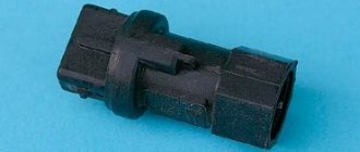
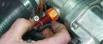
Old and new oxygen sensors
Old and new oxygen sensors
Posts 6
1 Topic by serega 32 2014-11-30 00:15:08
- serega 32
- New member
- Inactive
- Registration: 2014-11-29
- Messages: 5 Thanks : 0
- Car: VAZ 2109i
Topic: oxygen sensor connector is broken, how to connect by color? VAZ 2109
The connector has come off. How can I now connect the wires without this connector? Which wire goes to which? they are not there by color. Tell me who has encountered this!?
Added: 2014-11-30 01:15:08
I forgot to say, the car is a VAZ 2109i
2 Reply from Serg 2014-11-30 08:52:53 (2014-11-30 08:59:27 edited by Serg)
- Serg
- Lada2111.rf fan
- Inactive
- Registration: 2013-07-29
- Messages: 830 Thanks : 363
- Car: 2111 dwg 2114 year 2008
Re: oxygen sensor connector is broken, how to connect by color? VAZ 2109
Which side did the sensor or harness come off from? The connector has the letters ABCD
sensor A - C sensor output (gray and black) B - D sensor heater (usually white wires)
harness A - pink to ecu 28 leg B - pinkblack +12v heater power supply C - red and white to ecu 10 leg D - white to ecu
3 Reply from serega 32 2014-11-30 11:41:24
- serega 32
- New member
- Inactive
- Registration: 2014-11-29
- Messages: 5 Thanks : 0
- Car: VAZ 2109i
Re: oxygen sensor connector is broken, how to connect by color? VAZ 2109
Thank you. only there is no connector itself, just wires hanging. 4 from the sensor and 4 from the harness.
Publication date: January 16, 2021. Category: Automotive equipment.
Lambda probe (also called oxygen controller, O2 sensor, DC) is an integral part of the exhaust system of vehicles that meet EURO-4 environmental standards and higher. This miniature device (usually 2 or more lambda probes are installed) monitors the O2 content in vehicle exhaust mixtures, thereby significantly reducing the emission of toxic waste into the atmosphere.
If the DC is not operating correctly or if the lambda probe is disconnected, the functioning of the power unit may be disrupted, causing the engine to go into emergency mode (the Check Engine light will light up on the panel). To prevent this from happening, the car system can be outsmarted by installing a decoy.
Description, principle of operation
The basis of the sensor design is a solid gas-tight electrolyte, which is a ceramic material made of zirconium dioxide and yttrium oxide. The internal and external surfaces of the element are covered with porous platinum, which acts as electrodes.
The device is installed in the exhaust manifold, where it is heated by exhaust gases to a temperature of 300-400 degrees. The heated sensor becomes conductive for oxygen ions and begins to function.
The element becomes most effective and reliable at temperatures above 350 degrees.
The lambda probe compares the oxygen concentration in the exhaust gases with the oxygen content in the internal chamber. The internal chamber of the device is isolated from the exhaust flow and communicates with the surrounding air, which is used as a control gas. Due to the receipt of different oxygen concentrations, a potential difference occurs, which is transmitted in the form of signals to the engine control system.
Mechanical snag of the lambda probe (“screw-in”)
“Vvertysh” is a bushing made of bronze or heat-resistant steel. The inside of such a “spacer” and its cavities are filled with ceramic chips with a special catalytic coating. Due to this, the exhaust gases are burned faster, which, in turn, leads to different indicators of pulses 1 and 2 DC.
Important! Any snag is installed only on a working lambda probe.
A homemade lambda probe decoy, the diagram of which is presented below, is easy to manufacture. To do this you will need to prepare:
The blende is made on a processing lathe. If there is none, then you can contact a specialist by providing him with a drawing.
The resulting part is compatible with most exhaust systems of both domestic and foreign cars.
Installation of the lambda probe blende is carried out as follows:
- Lift the car onto the overpass.
- Disconnect the negative terminal on the battery.
- Unscrew the first (upper) probe (if there are two of them, then remove the one located between the catalyst and the exhaust manifold).
- Screw the lambda probe into the spacer.
- Reinstall the "advanced" sensor.
- Connect the terminal to the battery.
Healthy! Typically, mechanical blending of the second lambda probe is not performed, since this DC is protected by a catalyst and only controls its condition. The most sensitive is the first sensor, which is installed closest to the collector.
After this, the “Check Engine” system error should disappear. If this method does not work, you can use a more expensive deception.
Replacing the oxygen sensor
For various reasons, car owners unsolder the brake pads for the VAZ 21102. Some due to the replacement of an LZ that has a different connector from the original, others to install a non-standard exhaust manifold, which requires extending the wire. In any case, you should take care of insulation and high-quality wiring, for example as in the following photos:
Insulation example 1
Isolation Example 2
Replacement procedure
- Disconnect the oxygen sensor connector and unscrew it.
Advice! When unscrewing the LZ, you must use either a long head or a spanner. Since the LZ is most likely “burnt”, it must first be “soaked” with special auto chemical products.
Advice! For those who are not afraid of anything, unscrew it with the engine running until a slight smoke appears through the threaded part, then turn off the engine and unscrew it completely.
This method is directly related to the property of bodies to expand when heated and compress when cooled (textbook “Physics 5th grade”, page 40, paragraph 7, paragraph 2):
- We cut off the wires from the old one and connect them with the wires of the new sensor cut off from the block (standard colors and purposes of the wires are given earlier in the pictures);
Advice! For a three-wire standard LZ, the wires are written on the connector: heating - wires “A” and “B”, signal “C”. The polarity of the white heater wires does not matter; the signal wire is black.
- We remove the unused fourth wire from the harness and securely attach it to the vehicle ground, for example, to the bolt securing the brake master cylinder bracket;
- We screw in a new lambda probe (the three-wire probe is lubricated with graphite grease for better contact with the exhaust manifold body);
Advice! It is best to do the wiring of the block for the VAZ 2110 before installing the oxygen sensor in place, it is safer and more reliable.
- We reset the memory of the electronic control unit and check the operation of the new lambda probe.
At this point I consider this instruction complete. I didn’t add a video, I hope I made everything clear and simple. Good luck.
A modern car is an electromechanical system that consists of many parts and assemblies that are interconnected by a combination of various sensors. These sensors maintain the operating condition of the car and ensure its productive operation. Today in this article we will talk about the oxygen sensor (lambda probe). In particular, we will answer the question of how to check a lambda probe with 4 wires with a tester. This is the most common type of sensor and is quite important. Before you begin studying and testing the performance of the LZ, we recommend that you briefly study its design features, types and principle of operation.
Electronic snag
Another way to eliminate problems with the DC is to use an electronic decoy of the lambda probe, the diagram of which is presented below. Since the oxygen sensor transmits a signal to the controller, a decoy circuit connected to the wiring from the sensor to the connector will “crude” the system. Thanks to this, in a situation where the lambda probe is faulty, the power unit will continue to operate correctly.
Healthy! The installation locations for such deception may differ depending on the PBX model. For example, it can be mounted in the central tunnel between the seats, in the dashboard or in the engine compartment.
The decoy circuit is a single-chip microprocessor that analyzes the processes in the catalyst, receives data from the first DC, processes it, converts it to the indicators of the second sensor and issues a corresponding signal to the car processor.
Reflashing the controller
Some particularly sophisticated car owners decide to reflash the control unit, which blocks the processing of signals from the second oxygen sensor. However, it must be taken into account that any changes to the system operation algorithm can lead to irreversible consequences, since returning the factory settings will be almost impossible and costly. Therefore, it is not recommended to perform such manipulations yourself. The same applies to ready-made firmware that is sold on the Internet.
Healthy! When flashing the lambda probes, they are removed.
If you still want to flash the system, then contact a competent specialist who can disable receiving DC data using specialized equipment.
It is also worth considering that almost any intervention in the operation of systems can lead to not the most pleasant consequences.
What are the consequences after installing decoys?
You need to understand that any deception is installed at the risk of the car owner. If the installation was carried out incorrectly, you may encounter the following problems:
- Due to the fact that the on-board computer cannot regulate fluid injection, engine malfunction may occur.
- If the circuit is not properly soldered, it may damage the wiring.
- In the process of installing the decoy, you can damage the oxygen sensors, after which you will not even know about their malfunction (since you will already have the decoy installed).
- After such interventions (not only during flashing), the on-board computer may fail.
Any inaccuracy will lead to disastrous consequences, so it is better to install a safer ready-made emulator. Unlike deception, it does not “deceive” the control unit, but only ensures its correct operation by converting the DC signal. A microprocessor is also installed inside the emulator (as in a homemade electronic decoy), which is capable of assessing exhaust gases and analyzing the situation.
LADA VESTA. DIAGNOSTIC OXYGEN SENSOR (DOC) OF ENGINE 21129 WITH M86 EURO-5 CONTROLLER
content .. 120 121 122 123 124 125 126 127 128 129 ..
LADA VESTA. DIAGNOSTIC OXYGEN SENSOR (DOC) OF ENGINE 21129 WITH M86 EURO-5 CONTROLLER
To reduce the content of hydrocarbons, carbon monoxide and nitrogen oxides in the exhaust gases, a catalytic converter is used (see section 1.9).
The neutralizer oxidizes hydrocarbons and carbon monoxide, causing them to be converted into water vapor and carbon dioxide. The neutralizer also reduces nitrogen from nitrogen oxides.
The controller monitors the redox properties of the converter by analyzing the signal from the diagnostic oxygen sensor installed after the converter (Fig. 1.1-06). DDC works on the same principle as UDC. The UDC generates a signal indicating the presence of oxygen in the exhaust gases at the inlet of the converter.
The signal generated by the DDC indicates the presence of oxygen in the exhaust gases after the converter. If the neutralizer is operating normally, the DDC readings will differ significantly from the UDC readings.
The output signal of a warmed-up diagnostic oxygen sensor when operating in feedback mode, with a working converter in steady state, should be in the range from 590 to 750 mV and should not repeat the UDC signal. If a malfunction occurs in the circuits or the diagnostic oxygen sensor itself, the controller stores its code in its memory and turns on the alarm, signaling the presence of a problem.
The maintenance requirements for the DDC do not differ from those described above for the UDC.
LADA VESTA. CRANKSHAFT POSITION SENSOR (CPKV) OF ENGINE 21129 WITH M86 EURO-5 CONTROLLER
The crankshaft position sensor is installed on the oil pump cover (Fig. 1.1-07) at a distance of 0.9±0.5 mm from the top of the tooth of the drive disk mounted on the engine crankshaft.
The drive disk is combined with the generator drive pulley and is a gear with 58 teeth spaced at 6° pitches and a “long” synchronization cavity formed by two missing teeth.
When the middle of the first tooth of the toothed sector of the disk after the “long” cavity is aligned with the DPKV axis, the engine crankshaft is in position 114° (19 teeth) to the top dead center of the 1st and 4th cylinders.
- 1 - crankshaft position sensor
- When the drive disk rotates, the magnetic flux in the sensor's magnetic circuit changes, inducing alternating current voltage pulses in its winding. The controller determines the position and speed of the crankshaft by the number and frequency of repetitions
Briefly about the lambda probe
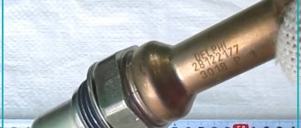
I can assume that the oxygen sensor is perhaps the most popular among all other car sensors that auto repair shop diagnosticians have to deal with. As you can see in the photo, the lambda probe (also known as an oxygen sensor) is made of a ceramic element (zirconium based) and coated with platinum. This galvanic element, depending on the presence of oxygen and temperature in the environment, changes its voltage and transmits data to the electronic control unit. Since the zirconium tip more accurately reads the presence of oxygen at a temperature of at least 360 degrees Celsius, a heating element is built into the lambda probe, which turns on when the engine starts and helps to quickly warm it up.
Visual inspection
The check should always begin with a visual examination of the condition of the oxygen sensor.
- Inspect the wires. They must be intact, without traces of damage or defects. Check all connectors for tight connections.
- Soot on the lambda probe indicates a malfunction of the device heater. Also, such deposits are caused by an excessively rich air-fuel mixture.
- If you notice shiny deposits on the surface of the element, this indicates an excess of lead in the fuel you are filling the tank with. This situation requires mandatory replacement of the oxygen sensor, since lead could damage the internal device.
- Gray or white deposits are the result of various types of fuel additives affecting the sensor. They often cause the probe to break and have to be replaced.
Repair
Diagnostics
The VAZ 2110 lambda probe has four outputs:
Pads for VAZ 21102
Checking the oxygen sensor heater comes down to a basic check of the heater circuit:
- the presence of voltage at the power contact of the vehicle’s on-board network (if there is no voltage, check the entire circuit);
- presence of continuity of the negative contact circuit.
In the future, we are exclusively interested in the signal wire, or rather, the change in voltage passing along it from the sensor to the ECU during various engine operating modes. You can check the operation of the sensor in two ways:
- Using a voltmeter;
- Using an oscilloscope (motor tester).
Since this instruction is intended for the common man who simply cannot have professional equipment in principle, we will diagnose the sensor using a voltmeter.
Method one: reading trouble codes
In order to read the fault codes located in the controller’s memory, it is necessary to either connect special diagnostic equipment to the diagnostic block (located on the left side under the instrument panel console) (too simple - not for us), or close contact “B” to ground, which is so The same can be done by connecting contacts “A” and “B”.
Diagnostic block VAZ 2110
- “A” - contact connected to the vehicle ground;
- “B”—controller signal contact;
- “G” — control of the VAZ fuel pump;
- “M” is a contact for issuing information (serial data).
After these contacts are closed, turn the ignition key to position “III” (do not start the engine), observe the “CHECK” indicator, which should flash the number 12:
- Flash;
- 1-2 second pause;
- Flash;
- Flash;
- Long pause of 2-3 seconds;
- Double repetition of the above cycle.
Reading fault code number “12”
Attention! This code indicates that the self-diagnosis program is running, otherwise this program does not work.
After this, the program displays codes of existing faults in a triple cycle (each code three times), in the absence of these, code “12” continues to be displayed constantly.
Attention! When the diagnosis is completed, these contacts are allowed to be opened only after the ignition is turned off, after ten seconds.
Erasing fault codes from the ECU memory in order to make sure that the fault has been eliminated occurs by turning off the controller's power for at least ten seconds. The power is turned off either by disconnecting the negative terminal from the battery or by removing the controller fuse.
Attention! Operations with power supply to the controller must be carried out strictly with the ignition off!
Method two: checking changes in LP parameters
So, let's get to the “delicious” part:
- We connect the negative probe of the voltmeter to the car body;
- We connect the positive probe to the signal wire of the lambda probe;
- Warm up the engine to operating temperature;
- We warm up the sensor itself by setting the engine speed to 2500 - 3000 rpm for three minutes.
We observe the sensor:
- It must turn on, that is, the voltage must be in the range of 0.8 - 1.0 volts and turn on at a frequency of 8 - 10 times every ten seconds;
- If the voltmeter shows a value of 0.45 volts and it does not change, then the sensor does not work - replace it;
- When the damper is opened sharply, the voltage should jump to about one volt, and when closed sharply, it should drop to almost zero.
Design and functions of the VAZ 2110 oxygen sensor
There are frequent cases when the oxygen sensor on a VAZ 2110 begins to malfunction. As a rule, this happens after a solid mileage. Let us immediately note that malfunctions of the lambda probe, as this sensor is often called, cannot be repaired; only replacement will help.
Old and new oxygen sensors Old and new oxygen sensors
Purpose of the lambda probe
The oxygen sensor has a significant impact on the stability of the engine, as well as on economical fuel consumption and minimizing the emission of harmful substances into the atmosphere. In principle, if it malfunctions, the VAZ 2110 will not stand rooted to the spot, but it will work much worse.
For example, it has been proven that the CO content in the exhaust gases if this sensor breaks down will not be within 0.3%, as the standards say, but 3, or even 7%.
Therefore, the sooner a failed device is replaced, the better.
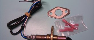
New Bosch lambda probe
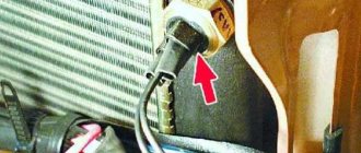
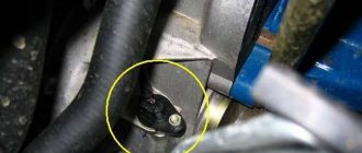
The oxygen sensor is installed on the exhaust pipe of the muffler, in its lower part. It measures the amount of oxygen in the exhaust of the VAZ 2110 engine and transmits a signal to the electronic control unit. And the controller regulates the optimal duration of the injection phase, adjusting the composition of the fuel mixture.
Without going into complex details, we can say that if there is oxygen in the exhaust, it means the mixture is lean; if it is completely absent, it means it is enriched. And the ECU controls everything so that it is optimal for a given specific engine operating mode.
Life time
According to the recommendations of the manufacturers, replacing the oxygen sensor for the VAZ 2110 should occur for unheated lambda probes every 50 - 80 thousand kilometers, for heated ones - after 100 thousand.
But this does not mean that malfunctions cannot appear earlier:
- The most important possible reason is carbon deposits under the protective cap; Oxygen sensor with carbon deposits on the working part Comparison of a new and dirty lambda probe
- Circuit breaks;
- Overloads (overheating) during ignition failures;
- Closure;
- Mechanical failure of the device due to careless driving.
Symptoms of breakdowns
The following symptoms will help you suspect a malfunction of the lambda probe on a VAZ 2110:
- Acceleration dynamics (throttle response) deteriorate;
- Idling floats;
- Fuel consumption is growing;
- Increased exhaust toxicity.
Changing the device
Since the oxygen sensor is not repairable, it requires routine replacement. The work is carried out on an overpass, pit or lift. You just need to disconnect the connector and use a 22 mm wrench to unscrew the device. The new one is installed in the reverse order.