Why do you need an on-board computer?
In previous articles we have already talked about what an on-board computer is, what it is needed for and what types they come in. But let me repeat myself so that you clearly understand all the advantages of having an on-board computer, and there are probably no disadvantages, except perhaps spending money on the purchase and that’s all.
Let's take, for example, the on-board computer STATE 115×24. With this model in your possession, you can:
- set the radiator fan start temperature; this function is very useful, for example, in winter, when you can control the temperature of the coolant, thereby monitoring the temperature of the heater radiator.
- The function of drying and warming up the spark plugs before starting the engine is very useful.
- The function of resetting settings and ECU adjustments is needed to switch to gasoline with a higher or lower octane number (from 92 to 95 and vice versa), and this function is also needed to reset settings after a long trip with increased load on the engine.
- The ability to read errors allows you to monitor the condition of the car and change non-working sensors and elements in a timely manner.
Installation instructions for on-board computer
In this article we will look at the process of installing the Prestige on-board computer with diagnostic and error reading functions.
For work we will need:
- Screwdrivers,
- on-board computer,
- wire 1m long.
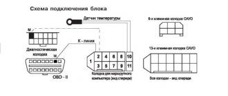
We remove the plug on the central dashboard and look for a 9-pin wiring block in it. This block must be present on all cars of our model. All that remains is to connect the block to the computer and that’s it, but we need to draw a K-line.
How to draw a K-line?
- We take our wire and install it in the second contact of our block.
- We throw the opposite end of the wire under the instrument panel down to the diagnostic block (for convenience, you can unscrew the right side panel).
- Having stretched the wire to the diagnostic block, we connect it to the “M” socket if you have a EURO-2 block or to the 7th socket if you have a EURO-3 block (it is very common that the diagnostic block for Euro-3 is installed upwards on the car feet, keep this in mind)
- Now we connect the on-board computer, insert it into its normal place and check it.
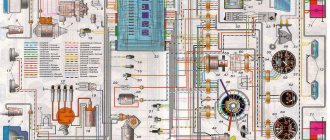
For a more complete and clear idea of the work, a diagram is presented.
What to do if there is no socket for the on-board computer under the instrument panel?
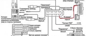
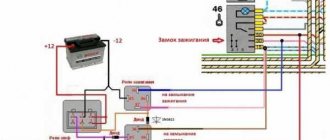
In this case, all that remains is to assemble a new block: buy a 9-pin block and run wires to it according to the following diagram:
- fuel consumption signal (green wire)
- ignition (orange wire)
- + 12 volts (red/white wire) red wire with white stripe
- mass (black)
- speed sensor (brown wire)
- 6k line (most often gray or black wire)
- mute (green/red wire) green wire with a red stripe
- backlight (white wire, or can be taken from the size button)
- fuel level sensor (pink)
OBD2 pinout - 16 PIN
Description:
The OBD2 connector is trapezoidal and consists of 16 pins.
Brands and years:
Gasoline passenger cars and light commercial vehicles manufactured or imported into the United States since 1996 (US CARB and EPA legislation) and in Europe (EOBD) since 2000-2001 (European Union Directive 98/69EG) and Asia (mainly since 1998). ).
Access and location:
Pinout:
| 1 | 2 | 3 | 4 | 5 | 6 | 7 | 8 |
| 9 | 10 | 11 | 12 | 13 | 14 | 15 | 16 |
| Smaller side of trapezoid | |||||||
Example in the photo:
Conclusions and their purpose:
| № | Color | Purpose |
| 2 | J1850 Bus + | |
| 4 | Body grounding | |
| 5 | Signal Ground | |
| 6 | Line CAN-High, J-2284 | |
| 7 | K-line diagnostics (ISO 9141-2 and ISO/DIS 14230-4) | |
| 10 | J1850 Bus- | |
| 14 | Line CAN-Low, J-2284 | |
| 15 | L-line diagnostics (ISO 9141-2 and ISO/DIS 14230-4) | |
| 16 | Power supply +12V from battery |
Diagnostic connector pins for used protocols
Pins 4, 5, 7, 15, 16 - ISO 9141-2.
Pins 2, 4, 5, 10, 16 - J1850 PWM.
Pins 2, 4, 5, 16 (without 10) - J1850 VPW.
The ISO 9141-2 protocol is identified by the presence of pin 7 and the absence of pins 2 and/or 10 on the diagnostic connector.
If pin 7 is missing, the system uses the SAE J1850 VPW (Variable Pulse Width Modulation) or SAE J1850 PWM (Pulse Width Modulation) protocol.
All three data exchange protocols operate via a standard OBD-II J1962 connector cable.
The correct connection diagram for a 12 PIN block with a 16 PIN adapter
Errors when connecting/operating the on-board computer
Error: “No connection with the controller” or “break in the K-line.”
This error indicates that the K-line is not connected or a contact break has occurred. Check the wire according to the diagram described above. Most likely the contact has come off the diagnostic block.
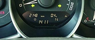
Error: Incorrect readings of the sea temperature sensor.
If your temperature outside is -40, then this indicates that the wire to the temperature sensor has broken, or there is no such sensor at all. If the temperature is, for example, -25, but it’s only -10 outside, then you need to replace the sensor with a working one.
Pinout
Knowledge of pinouts may be required if a car enthusiast wants to make an adapter for computer diagnostics with his own hands, or if you need to connect without one. Experts recommend buying ready-made devices without the need to make a plug yourself. However, if you do not have such an opportunity, and diagnostics need to be carried out urgently, we will consider two main pinout options used on VAZ cars of various years of manufacture. Until 2002, AvtoVAZ products used the following pinout option:
- The 4th and 5th pins are GND outputs.
- Pin 16 – +12 V (power line).
- The 7th contact is the diagnostic line itself.
Since 2002, the pinout scheme has changed significantly. Now it looks like this:
- Pin H – +12 V (power line).
- Contact G – +12 V for the fuel pump.
- Pin A – GND output.
- Contact M – diagnostic line.
How to install an on-board computer on a VAZ 2114
Not so long ago, on Russian cars, all parameters were monitored by arrows on the instrument panel. Using the instruments, one could find out the speed, the presence of fuel in the tank, the temperature of the liquid in the cooling system, oil pressure, and charging. But all the data was quite approximate, and there were not so many parameters. Recently, many modern passenger cars have increasingly become equipped with more advanced control means, and there are more and more such devices. Nowadays, modern technology allows us to more accurately monitor the technical condition of a vehicle and timely identify any problems in it.
Basic information
The functionality of this device provides a lot of possibilities. Using the on-board computer on the VAZ-2115, you can determine almost all engine operating parameters. What allows you to control the device:
- Vehicle speed at the current time, average value, minimum or maximum.
- Fluid temperature in cooling systems and braking.
- The magnitude of the voltage in the on-board network.
- Fuel consumption per 100 km. Moreover, you can display both the average value and the current, maximum, minimum.
- Gasoline level in the fuel tank.
These are just a few of the parameters that electronics can monitor. Using the on-board computer on the VAZ-2115, you can also check the status of all sensors of the injection injection system. Moreover, the operating instructions for the device must contain information about which error code corresponds to the malfunction of a particular sensor.
By installing such a trip computer on your car, you can get rid of visits to auto repair shops the first time the CHECK ENGINE light comes on. Every time you turn on the ignition, you see before your eyes all the errors that are present in the car’s systems. If necessary, you can erase them.
Source
PURPOSE OF THE ON-BOARD COMPUTER
An on-board computer on a car is an electronic computer device designed to monitor the status of various components of the car and transmit information to the car owner. Depending on the technical equipment, on-board computers (BCs) can vary in complexity, and accordingly, the price of the device can vary significantly.
The VAZ 2114 car is equipped with BC 2114-3857010 as standard from the factory. The device is mounted on the panel to the right of the instrument cluster at the same level with it. On those VAZ models that are not equipped with such a device, there is a plug in the standard place on the instrument panel and there must be a 9-pin connector for connecting the device.
In the “native” BC 2114, you can view the following parameters on the display:
- Current time and date;
- Travel time excluding stops;
- Travel time, including stops;
- Gasoline consumption at the current time;
- Average and total gasoline consumption per trip;
- Mileage on the remaining gasoline in the tank;
- Signal when there is a minimum amount of fuel left in the gas tank;
- Total level of remaining fuel;
- Travel distance;
- Average speed during the trip;
- Vehicle network voltage;
- Signal when the mains voltage is below the permissible level.
The “Lux” package is equipped with an AMK-211501 on-board (or route) computer, which has added firmware that allows you to diagnose the electronic engine control system (ECM). But many owners of VAZ models 2113, 2114, 2115 are not satisfied with the standard equipment with its limited functionality, and they strive to install a more advanced BC with a larger set of controlled parameters. They can be understood - now there are many different models from different manufacturers.
The smallest BC State X-1M is made in the form of buttons.
BC State X-1M
It is mounted above the standard location of the trip computer instead of push-button plugs. Among the interesting additional functions of the device are:
- “Plasmer” – warming up the spark plugs before starting the engine;
- “Tropic” – the ability to change the temperature at which the fan turns on and thereby prevent engine overheating in hot weather.
In total, the device has 30 functions, and the BC costs about 1000 rubles. More expensive trip computers are installed in a standard place and are more functional. On the display of the Orion BK-46 model you can see up to 7 controlled parameters simultaneously, and when the battery is disconnected, all data is saved in memory in the device. The issue price is about 2500-2800 rubles.
One of the most advanced BC models for the VAZ 2114 is the “Gamma GF 415T”. Here you can see interesting features such as:
- Displaying three multi-displays on the screen at once;
- Non-volatile quartz watches;
- Informing about the need to change oils, filters, spark plugs, etc.
There are a lot of controlled parameters, the cost of a bookmaker is in the range of 4000-4600 rubles. Many systems are equipped with audible alerts, and these computers are very easy to use.
How to connect and configure the VAZ-2115 on-board computer
Content
- General principles for connecting a computer
- Step-by-step installation of a computer on a VAZ-2115
- What capabilities should an on-board computer have?
- Hazard warning light - practical or not
- Installing an on-board computer - Sigma format
The dashboard of the VAZ-2115 has a pre-designed space for the subsequent installation of an on-board computer. In this case, if you need to install a control device in a car, then there is no need to change the design of the torpedo, but rather use a standard socket.
The on-board computer provides comprehensive information to the driver about the following indicators:
- Vehicle movement mode.
- Gasoline consumption.
- The state of the car's electrical network and so on.
In addition to information capabilities, such a device is capable of diagnosing the state of the internal combustion engine control system. Certain types of on-board vehicles can be installed on cars with carburetors. However, for everything to work, you will need to additionally install a number of sensors.
In the modification of the VAZ-2113, a computer is installed that interacts with the controller of the internal combustion engine control system. Its task is to process all incoming information and display the main indicators on the screen in an understandable form.
Automotive stores today sell a wide variety of such devices, which differ in their functionality and location in the car.
All functions of the device in question are divided into two parts:
- Informational.
- Diagnostic.
To enable the required operating mode, use seven buttons on the device panel:
- Pressing this button tells the computer that the ride has begun. The same element resets the accumulated information in memory.
- + and – are designed to adjust the values of various characteristics when the device is in setup mode, as well as to study information about the state of specific components of the car.
- In addition to display functions, the on-board computer can produce sound signals when the actual parameter values exceed the maximum permissible standards. This is a kind of emergency signal.
These are not all the functions of the device in question, but only the main capabilities. Next, we will look at the process of installing a computer in a car.
CONNECTION
The connection diagram for the on-board computer on the VAZ 2114 is simple - it does not require special training or special qualifications. Therefore, you can connect the on-board computer to the VAZ 2114 with your own hands; detailed instructions are always attached to each device.
The connection principle is the same for all BCs, so let’s take a closer look at how to install an on-board computer on a VAZ 2114:
- De-energize the car (disconnect the battery terminals).
- We remove the standard plug from the instrument panel.
- We find the 9-pin connector.
- Remove the plug for the diagnostic connector.
- Remove the lower left side of the center console on the instrument panel.
- We take a piece of wire (about 1 m long) and connect it according to the following diagram. This wire in the diagram is designated as K-line white. That is, we connect terminal “7” (Euro-3) or terminal “M” (Euro-2) in the diagnostic connector with terminal “2” in the BC block with a wire.
The top right shows the Euro-3 type diagnostic connector (newer version), the bottom right shows the Euro-2 connector. The wire connection to the connectors is shown below. Connecting the on-board computer wire to the connectors We connect the BC connectors. Connection of BC connectors on VAZ 2114
- We install the BC in its regular place.
That's all, the installation of the on-board computer on the VAZ 2114 has been completed.
Preparing for installation
Before you begin installation, you need to do some preparatory work:
- Decide what parameters you want to receive from the BC, because the number of connected wires depends on this choice. To do this, we suggest that you read the instructions in more detail, and if you don’t have them, you can always find information on the Internet.
- Decide on the installation location of the BC, and if this is a standard location on the VAZ-2114, then the model should be selected in the appropriate size.
- Remember that after installing the BC, it will periodically need to be connected to a computer or laptop to download updates, so it is still not worth sealing and securing it tightly at the installation site.
SETUP AND TROUBLESHOOTING
Setting up the on-board computer is not always required; for example, the BC 2114-3857010 is easy to use and requires almost no settings. Each device displays its own parameters, so you need to read the instructions for the BC and follow the recommendations from the manufacturer.
If the VAZ 2114 on-board computer does not work, you need to check:
Sometimes it is necessary to reset all data (fuel consumption, travel time, etc.). As a rule, the instructions contain instructions for this (usually a reset button). But if there is no instruction or it doesn’t say anything about it, then you can reset the indicators like this:
- Remove the BC and remove the connector for a while;
- Disconnect the battery terminals for a certain period of time.
The readings should reset to zero.
ERRORS
On the on-board computer you can read all the errors that occur in the ECM. Deciphering the VAZ 2114 error code follows certain codes. If there are no errors, the message “No errors” lights up on the display. The list of errors is large, so we will list only the most common error codes for the VAZ 2114:
- 0134 – no oxygen sensor activity;
- 0116 – coolant temperature sensor error;
- 0172 – enriched fuel mixture;
- 0300 - presence of misfires;
- 0340 – phase sensor is faulty;
- 0505 – failures in the XX regulator.
Errors on the VAZ 2114 on-board computer are reset according to the instructions for each specific model by pressing a button combination, but a general reset can be done by temporarily disconnecting one of the battery terminals.
BC errors
If you buy a car that already has an onboard vehicle installed, this is quite good. You don't have to install it yourself.
Plus, it's a great way to check whether the car is as good as the owner claims.
To check the BC for errors, reset the daily mileage on the dashboard and at the same time turn on the ignition. Then press the button located near the windshield wiper lever. The display will show the firmware version of the installed BC, plus error codes, if any.
The main bookmaker errors are shown in the table. Moreover, the most popular of them, which are found on the VAZ 2114, are 4, 6 and 8.
| Code | What does it mean |
| 2 | The car's mains voltage is too high |
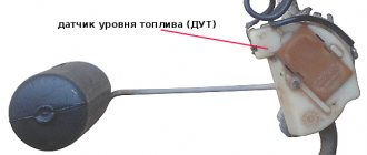
| 3 | Fuel level sensor is faulty |
| 4 | The coolant temperature sensor has failed |
| 5 | The outside temperature sensor is faulty |
| 6 | The engine gets very hot |
| 7 | Oil pressure has reached a critically low level |
| 8 | There are problems with the braking system |
| 9 | The battery is low |
Once errors are detected, appropriate decisions can be made. If we are talking about your car, simply reset the data by pressing and holding the daily mileage button. Without doing this, the errors will persist during the next diagnosis, although you have taken measures to eliminate them by repairing the corresponding components of the car.
Diagnostic connector VAZ 2114: purpose, location and preparation for diagnostics
The VAZ 2114 diagnostic connector is required to connect the on-board computer. The VAZ 2114 diagnostic connector is in high demand among car enthusiasts, because it makes vehicle operation more convenient. There are many computers that will suit the VAZ. They can be connected to the car using this connector.
In most cases, there are instructions for using the device and connecting. But drivers often use used products that do not have the appropriate documentation. In this case, you will need information about where exactly the connector is located and how to install it.
Where is the correct connector?
Most often it is located under the torpedo. By the way, it can be located on both the right and left sides. On certain models, the device is located near the steering column. Can be located to the left and below it. For cars that have a Europanel, the connector is located under the cigarette lighter.
Attention! The required connector can be covered with a decorative panel.
It is worth mentioning that two additional contacts, which are located on the diagnostic block of the VAZ 2114, are needed for the external air temperature sensor. After you make the connection, you will need to activate the K-line. It is necessary in order to transfer all important information to the device.
This is done as follows:
- The meter wire is connected to the second contact of the connector block.
- The second end is led to the diagnostic connector.
- The connection is made using the M-socket at the EURO 2 block, or to the seventh socket of the EURO 3 block.
- Connect the on-board computer and install it in the planned location.
Pinout of diagnostic connectors for VAZ and GAZ cars
Currently, the vast majority of cars have an OBD2 diagnostic connector (trapezoidal 16-pin block, usually located in the steering wheel area). Through this connector you can connect diagnostic equipment to diagnose your car, as well as connect on-board computers and other devices that work through the diagnostic connector.
People often have questions about the pinout of diagnostic blocks for some cars. Our store has various adapters for different models. But if you forgot to order an adapter for your car, you can try to make it yourself, or connect the adapter directly. To do this, we have prepared for you a short review on the pinout of the OBD2 socket, the pinout of the sockets for VAZ and GAZ cars.
OBD2 connector pinout
This option has been common in foreign cars since 2002, and is also installed in all VAZ cars after 2004.
Pin designations: 7 - K-diagnostic line 4/5 - GND protruding contacts 16 - +12V adapter power supply
Pinout of the VAZ block before 2002:
Contact designations: M - k-diagnostic line H or G - adapter power supply +12V
When connecting an adapter without a block directly to the wires, it is better to take power from the cigarette lighter, since the contact shown in Figure H, depending on the model, may not be routed, and when using the G contact, the fuel pump gives very large impulses that can damage the adapter.
Pinout of GAZ/UAZ block:
Contact designations: 2 - Power supply of the adapter +12V 12 - ground 10 - L-diagnostic line (may not be wired, as a rule not used) 11 - K-diagnostic line
If you are interested in pinouts of connectors of other brands, you can refer to the specialized reference book.
Did you like the article? Save it for yourself!
Basic steps in diagnosis
When you have found the VAZ 2114 diagnostic connector, you can begin the required diagnostic work.
By the way, before installing the device, think about what exactly it will be used for. When choosing an on-board device, you need to take into account the characteristics of the car, so inexpensive models are suitable for the VAZ 2114. It will be enough to choose a system that has a monitor, a set of wires, and the processor itself.
Next, you will need to find a place where you can mount the monitor. It is necessary to take into account the individual characteristics of the machine; the optimal place is the central part of the console. When there is not enough free space on the dashboard, you should mount the monitor on the dashboard.
Remember that you need to find a place for the processor, and it is important that the ventilation holes must be freely accessible. The case should be fixed in a certain place for greater reliability.
The wires deserve special attention; they must not be damaged during operation. To do this, experts advise passing them through a special tube.
After the connector for diagnosing VAZs has been found, other work has been completed, and the wiring can be connected.
After the installation is completed, you can install the software and make the necessary settings.
Now you have access to car diagnostics.
OBD1 pinout - 12 PIN (GM12)
Description:
OBD1 (GM12) connector is rectangular in shape, consists of 12 contacts.
Brands and years:
All injection models, except for some models after 2002, which have an OBD-II connector.
Access and location:
Pinout:
| M | L | K | J | H | G |
| A | B | C | D | E | F |
| Key * | |||||
* Connector Keying - A design element of a removable connector that ensures the correct orientation of the plug and socket.
Diagnostic connector VAZ 2114: purpose, location and preparation for diagnostics
The VAZ 2114 diagnostic connector is required to connect the on-board computer. The VAZ 2114 diagnostic connector is in high demand among car enthusiasts, because it makes vehicle operation more convenient. There are many computers that will suit the VAZ. They can be connected to the car using this connector.
In most cases, there are instructions for using the device and connecting. But drivers often use used products that do not have the appropriate documentation. In this case, you will need information about where exactly the connector is located and how to install it.
Where is the correct connector?
Most often it is located under the torpedo. By the way, it can be located on both the right and left sides. On certain models, the device is located near the steering column. Can be located to the left and below it. For cars that have a Europanel, the connector is located under the cigarette lighter.
Attention! The required connector can be covered with a decorative panel.
It is worth mentioning that two additional contacts, which are located on the diagnostic block of the VAZ 2114, are needed for the external air temperature sensor. After you make the connection, you will need to activate the K-line. It is necessary in order to transfer all important information to the device.
This is done as follows:
- The meter wire is connected to the second contact of the connector block.
- The second end is led to the diagnostic connector.
- The connection is made using the M-socket at the EURO 2 block, or to the seventh socket of the EURO 3 block.
- Connect the on-board computer and install it in the planned location.
Broken wire to the line on a VAZ 2114. Do-it-yourself diagnostics using the K-line, part 1
The control unit is a microprocessor device and can transmit information about its operation via a serial communication channel.
The standard for such a channel in automotive electronics is the K-line. The diagnostic line is a means of transmitting information between the electronic unit and external devices: immobilizer, testing equipment, diagnostic devices. Communication with the immobilizer is established after turning on the ignition switch. The control unit and the immobilizer exchange via the K-line the parameters specified during training of the immobilizer. If the parameters meet the specified conditions, the electronic unit proceeds to the normal operation of the control algorithm. Failures and malfunctions in the communication lines with the immobilizer, mismatch of training parameters transfer the control program of the unit to a mode in which engine operation is impossible. The K-line in the car is connected to a diagnostic connector, to which a tester can be connected to diagnose the operation of the control system. The standard software protocol for data exchange between devices and the electronic unit, implemented in these devices, makes the operation of all devices connected to the K-line transparent. Lack of communication between the control unit and the diagnostic tool may indicate a malfunction of both devices. If there is no such connection, and confidence in the performance of the tester is beyond doubt, then the first step is to check the diagnostic circuit. First you need to make sure that there is power to the on-board network at the control unit and the K-line circuit from the control unit reaches the diagnostic connector. The voltage at the K-line terminal of the diagnostic connector, with a working circuit, is equal to the on-board network voltage. Since the K-line circuit is connected to the diagnostic connector through the immobilizer connector, checking the circuit should be carried out taking into account the serviceability of the immobilizer. If the immobilizer is not functionally involved in the system, it is best to connect the wires (K-line input and output) directly from the immobilizer connector. During the preparation of production, it was assumed that immobilizers would be installed on some cars with a control system based on blocks from Bosch. But mass production of immobilizers was not prepared in the required time frame. In this case, if the wiring harness provides for the installation of an immobilizer, the connection between the diagnostic output of the control unit and the diagnostic block is broken. To correct this situation, it is necessary to install a jumper between pins 9 and 18 of the immobilizer connector. On vehicles where the wiring harness does not provide for the installation of an immobilizer, this problem does not exist. Good day to everyone who is reading this entry! And so I’ll start with the fact that I don’t have an on-board computer, I have a desire to install it, but more on that later. There was an interest in identifying my car with my own hands. In one of the previous articles, I wrote that after a rainstorm I filled up the air flow sensor, the check light came on and I went for diagnostics: they charged me 100 UAH. Within 30 seconds, having discovered that the sensor does not work, it needs to be replaced. I don’t need professional diagnostics; if necessary, I’ll go to a diagnostician, and for easy diagnostics, I decided to buy a K-line scanner
VAG-Com 409.1 K – Line scanner
oh, and even though my car is from 2004, it is 1.5l and 8kl with EURO-2, and is equipped with an ODB-1 connector. I googled it: it turns out that ODB-2 was already installed but on 16kL cars with EURO-3 from earlier years. I also had to buy an adapter with
Adapter OBD-II 16pin to GM12
I ordered everything from the online store, along with the cords I received a disk with programs for diagnostics and a bunch of different information on diagnostics. I configured all the com ports on the laptop and went into the garage with the laptop to try. I plugged it in, turned on the ignition, bam, and the fuel pump immediately began to hum without stopping. Naturally, nothing happened and I abandoned the matter (and this was last year at the end of autumn). Well, it’s already warm - there is a desire to resume this business. When I rang the adapter, I didn’t really understand anything, one rings 3 at a time, some don’t ring at all, I decided to redo it all. As you know, for diagnostics via the K-line you only need 3 wires (channels): 1) potassium itself 2) +12V 3) -12V aka ground, ground
K-line connection
I would like to note that in the figure above the contacts on the adapter are drawn as they should be, and not on the adapter or block! So imagine applying the adapter and think about where the contacts on the adapter and block should be, here is the picture below
location of K-line contacts on the blocks
Lamaaat adapter! Well, what can you do, the design is not collapsible (breaking the connector turned out to be not an easy task))) the black body is very hard, everything inside is still filled with white plastic. 4 wires are soldered, everything is called where which goes to the adapter where is the K-line, +12 and ground, the fourth, judging by the continuity, is the L-line, which we do not need. I’ll connect these 3 wires directly to the diagnostic block and try to connect to the ECU again! Good luck for me! Read the continuation!
| Do not forget to disconnect the battery before performing any manipulations. Next, you need to get the trip computer itself (MK or BC). It is obtained in the same way as a watch, by prying it off with a screwdriver. The BC is held on by four plastic latching brackets, two at the bottom and two at the top. Next, you need to familiarize yourself with the bookmaker itself, with the inscriptions on the back side. Why this is necessary, I explain, initially the BC of the Kursk Schetmash (passport) (I can lie further, but as far as I understood everything exactly like this) was obliged to contact the K-line, but VAZ changed the technical specifications, and the firmware was cut off, i.e. the part responsible for communication with the ECU was simply cut out. |
|
| If there is a track, and when you press the 'clock' button in clock mode, nothing happens, then you have a full-fledged BC with defective firmware that needs to be updated (file 527-10.hex and instructions for the firmware are in the archive). You can update the firmware using standard means (by unsoldering the processor, it is there, by the way, PIC18F252, and flashing the firmware in the header, or by soldering the wires directly to the legs, I did this), or through the K-line from the PC. There is information that this did not work with all K-line adapters, plus for this you need to have Win 95-98, some did it on XP, but most had problems with XP. In order not to install Win 95-98 solely because of the BC firmware, you can use a virtual machine (thanks to Ivan Kuchinsky for the successful experiment). |
The K-line is connected to the BC block simply; fairly common contacts are used there. We prepare a contact with a wire, insert it into the BC connection block, and connect it to pin 7 of the OBD-II block. Next, select your controller in the settings, as described in paragraph 3.8.3 of the BC instructions:
- ECU.0 - M1.5.4
- ECU.1 - M1.5.4N or January-5.1
- ECU.2 - MP7.0
- ECU.3 - MIKAS 5.4, MIKAS 7.1, 301.3763 000-01
- ECU.4 - Bosch 7.97
Communication with the controller only when the ignition is on. Information does not appear immediately! We wait patiently from a few seconds to minutes.
By the way, it doesn’t work fully with Bosch 7.9.7, but there is an option to look at errors and reset it.
What I mean is that it is not indicated in the instructions at all. And yet, don’t be afraid to kill him! You will always have the opportunity to buy the same PIC18F252 processor and flash it (ask anyone who is interested in or works with microelectronics) separately, or solder it and flash it. But this does not at all negate the accuracy and thoughtfulness of actions! If you have any questions, I am ready to provide clarification. Instructions on how to check the VAZ K-line
10/11/2014 02:52
Most often, the solution to the problem really lies in breaking the K-line wire. That is, the wire has simply moved slightly out of the block (the APS block of the immobilizer, or the BC block) and there is no longer any contact.
If you have checked all the contacts, but the on-board computer still does not see the K-line wire, then you can proceed as follows:
1) Check the voltage on the K-line. We set the multimeter to the mode for measuring constant voltage, connect the red probe to the K-line, and the black probe to ground to any point on the body. The readings on the device should be 12+-2V. You cannot use a lamp to check the voltage, because it has a load.
2) If on your VAZ the connector with the APS is disconnected, then check for the presence of a jumper in the APS block between pins 9 and 18.
3) The problem may be in the immobilizer (the K-line signal comes, but disappears after the immobilizer). Check for the presence of a K-line on pin 18 of the APS block. Using the same method, you can check whether there is a break between the APS block and the BC block.
4) Interference or broken wire. Try replacing the wire from the BC to the diagnostic connector with a new, shorter one.
You can also check the k-line at a service center using computer diagnostics, or by connecting a known working on-board computer to the car. And if the k-line does not work and at the same time there are problems with starting the engine, then start checking the additional VAZ fuses.
Thematic materials:
What tires are suitable for the UAZ Bukhanka Standard UAZ Bukhanka tires The main parameters of wheels for a Hyundai Creta car What is the wheel offset for the Hyundai Gretta Decoding of symbols and abbreviations Cordiant Snow Cross is the best budget studded tire Lamels as a factor that increases traction What kind of tires are on the Mazda CX 5 Diesel land cruiser 100 Toyota land cruiser 100 new How to correctly convert inch wheel size to millimeters
103583
If you notice an error, select a piece of text and press Ctrl+Enter
Basic steps in diagnosis
When you have found the VAZ 2114 diagnostic connector, you can begin the required diagnostic work.
By the way, before installing the device, think about what exactly it will be used for. When choosing an on-board device, you need to take into account the characteristics of the car, so inexpensive models are suitable for the VAZ 2114. It will be enough to choose a system that has a monitor, a set of wires, and the processor itself.
Next, you will need to find a place where you can mount the monitor. It is necessary to take into account the individual characteristics of the machine; the optimal place is the central part of the console. When there is not enough free space on the dashboard, you should mount the monitor on the dashboard.
Remember that you need to find a place for the processor, and it is important that the ventilation holes must be freely accessible. The case should be fixed in a certain place for greater reliability.
The wires deserve special attention; they must not be damaged during operation. To do this, experts advise passing them through a special tube.
After the connector for diagnosing VAZs has been found, other work has been completed, and the wiring can be connected.
After the installation is completed, you can install the software and make the necessary settings.
Now you have access to car diagnostics.