Sensor layout
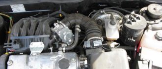
The sensors under the hood of the VAZ 2115 are located as follows.
1. Phase sensor; 2. Coolant temperature sensor; 3. Knock sensor; 4. Oil pressure sensor; 5. Oxygen sensor; 6. Crankshaft position sensor; 7. Speed sensor; 8. Idle speed sensor; 9. Mass air flow sensor; 10-11. Gasoline level sensor; 12. Antifreeze level sensor; 13. Throttle position sensor
Scheme of VAZ-2115 Lux configuration
The luxury package is a model with headlight cleaners, heated seats, electric windows, central locking, a trip computer and a fluorescent interior lighting.
- block headlights;
- gearmotors for headlight cleaners*;
- fog lights*;
- ambient temperature sensor;
- sound signals;
- engine compartment light switch;
- engine cooling fan electric motor;
- generator VAZ-2115;
- low oil level indicator sensor;
- washer fluid level sensor;
- front brake pad wear sensor;
- wire ends connected to the common windshield washer pump**;
- windshield washer pump;
- headlight washer pump*;
- wire ends for connecting to the rear window washer pump on VAZ-2113 and VAZ-2114 cars;
- low oil pressure indicator sensor;
- engine compartment lamp;
- wire lug for connecting to the engine management system wiring harness;
- windshield wiper gear motor;
- starter VAZ-2115;
- block connected to the wiring harness of the ignition system on carburetor cars;
- coolant temperature indicator sensor;
- reverse light switch;
- low brake fluid level indicator sensor;
- accumulator battery;
- low coolant level indicator sensor;
- relay for turning on fog lights;
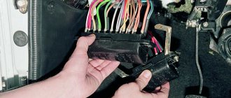
- mounting block;
- brake light switch;
- plug socket for a portable lamp;
- hydrocorrector scale illumination lamp;
- parking brake indicator lamp switch;
- block for connecting a backlight lamp;
- switch for instrument lighting lamps;
- Understeering's shifter;
- hazard switch;
- front seat heating element relay;
- ignition switch;
- rear fog lamp circuit fuse;
- front seat heating elements circuit fuse;
- door lock circuit fuse;
- front ashtray illumination lamp;
- ignition relay;
- cigarette lighter VAZ-2115;
- glove box lighting lamp;
- glove compartment light switch;
- heater fan motor;
- additional heater motor resistor;
- heater fan switch;
- heater switch illumination lamp;
- heater lever illumination lamp;
- gear motors for electric windows of the front doors;
- right front door ESP switch (located in the right door);
- gear motors for locking front door locks;
- wires for connecting to the right front speaker;
- gear motors for locking rear doors;
- wires for connecting to the right rear speaker;
- door lock control unit;
- wires for connecting to radio equipment;
- headlight wiper switch*;
- rear window heating element switch;
- rear fog light relay;
- block for connection to the heating element of the right front seat;
- rear fog light switch;
- right front seat heating element switch;
- fog light switch*;
- switch for external lighting lamps;
- left front seat heating element switch;
- block for connection to the heating element of the left front seat;
- wires for connecting to the left front speaker;
- left front door power window switch (located in the left door);
- right front door power window switch (located in the left door);
- wires for connecting to the left rear speaker;
- side direction indicators;
- dome light switches on the front door pillars;
- dome light switches on the rear door pillars;
- lampshade VAZ 2115;
- individual interior lighting lamp;
- block for connecting to the wiring harness of the electric fuel pump;
- trunk light switch;
- instrument cluster;
- trunk light;
- on-board control system display unit;
- trip computer*;
- block for connecting the wiring harness of the engine management system;
- rear exterior lights;
- rear interior lights;
- pads for connecting to the rear window heating element;
- license plate lights;
- additional brake signal located on the spoiler.
Numbering order of plugs in blocks:
A - headlight units and headlight cleaners; B - cigarette lighter; B - mounting block, instrument cluster, ignition switch, windshield wiper and other electrical components (for blocks with a different number of plugs, the numbering order is similar); G — relay for turning on the rear fog light; D — alarm switch; E — electric window motors and door lock motors; F — interior lamp.
In the instrument panel wiring harness, the second ends of the white wires are brought together into one point, which is connected to the instrument lighting switch (except for the white wire, from plug “4” of block “X2” of mounting block 28 to display block 83 of the on-board control system). The second ends of the black wires are also brought together to points connected to ground. The second ends of the yellow wires with a blue stripe are brought together to a point connected to plug “4” of the “X1” block of the mounting block. The second ends of the white wires with a red stripe are brought together to a point connected to plug “10” of the “X4” block of the mounting block. The second ends of the orange wires are brought together to a point connected to plug “3” of the “X4” block of the mounting block.
Explanations for the 8-pin injector block: white-red and blue - for the check light bulb, blue-red - ignition, gray - speed sensor, brown-red - tachometer, blue-white - driver's door switch (for the immobilizer), green- red - K-line (may not exist), green - fuel consumption. Next to it is a pink wire - to the fuel level sensor.
See the complete diagram in one file below (click to enlarge):
Electronic engine control unit
The engine control unit is a kind of head control center for the entire car. This device processes all the readings provided by the vehicle’s sensors, regulates the engine control process, determines the required fuel and air ratios, generates a spark supply to the desired cylinder, and much more. The ECU is located inside the car, under the dashboard.
Throttle sensor VAZ 2115
TPS is one of the key devices, the correct operation of which affects the functioning of the fuel system. This sensor transmits information to the car’s “brains” at what angle the throttle valve is currently located.
One of the main characteristics of TPS is the signal frequency. Based on changes in signal frequency, the engine control unit determines the degree of pressure on the gas pedal, which allows the “brains” to select the most optimal engine cooling mode and the amount of fuel supplied.
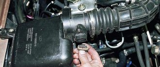
Mass air flow sensor
Mass air flow sensor is one of the most expensive sensors in a car. It is responsible for counting the air passing through it. These readings are necessary for proper mixing of air and fuel. The flow meter can fail if the air filter is not replaced for a long time, as well as with strong ventilation of crankcase gases due to the high content of oil combustion products in the internal combustion engine. It is located on the air filter housing and is attached to it with two bolts.
Signs of malfunction:
- Uneven idle speed;
- Increased fuel consumption;
- Long start of the internal combustion engine;
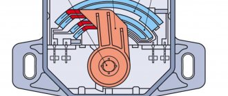
Phase sensor
It is responsible for adjusting fuel injection only into the cylinder that is in the compression stroke, that is, fuel is supplied only through one injector to one cylinder. It is oriented along the camshaft, which is why it is called the camshaft position sensor. It works according to the Hall principle, producing an electrical impulse when a magnetic field is excited. If the VAZ 2115 phase sensor fails, fuel is supplied according to the principle of carburetor engines - into two cylinders at once. The result is a set of faults.
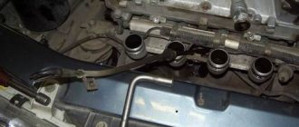
Symptoms of malfunction
The DPRV is located in the same place as the camshaft gear, on the cylinder head. The main symptom of the malfunction is high fuel consumption and loss of power. In addition, the computer displays error 0340 (sensor error) or 0343 (pulse level too high).
Examination
The malfunction of the DPRV can be judged by the error code and the burning CE lamp, but you can verify its functionality by checking the voltage at the power terminal A (12 V). The remaining terminals must not be live.
How to check the Hall sensor
A simple way to check the camshaft position (Hall) sensor is shown in the following video.
There are several ways to check the health of the Hall sensor. Each motorist can choose the most suitable option for himself:
- Take a working sensor from a neighbor or at a car disassembly for testing and install it instead of the “native” one. If the engine problems disappear, then you will have to buy a new part.
- Using a tester, you can measure the voltage at the sensor output. In a working device, the voltage will vary from 0.4 V to 11 V.
- You can create a simulation of a Hall sensor. To do this, remove the three-pin block from the distributor. Then turn on the ignition and connect outputs 3 and 6 of the switch with a piece of wire. The appearance of a spark indicates that the sensor has failed.
If the test reveals that the Hall sensor is faulty, then it must be replaced with a new one.
Crankshaft Positions
The VAZ crankshaft sensor is an element that allows you to transmit signals to the on-board computer about the position of the crankshaft. The performance of the combustible mixture supply systems, as well as the ignition system, depends on how this element works. And if we are talking about an injector, then the DPKV determines the functionality of the injectors.
This element is often called a synchronization regulator, since the control unit, having received data from it, detects the required moment of gasoline injection into the engine cylinders. If the device breaks down, the on-board computer will begin to transmit incorrect data, which will subsequently lead to malfunctions of the gasoline supply system. Accordingly, normal operation of the injectors will be impossible. The regulator itself is located next to the camshaft and the generator belt.
Throttle Positions
The throttle position sensor (abbreviated as TPS) is one of the main components that ensures the normal operation of the fuel system. From the name you can guess that the VAZ throttle controller transmits data to the on-board computer about what angle the throttle is currently at. The symptoms of the breakdown and the process of replacing the device are described in more detail in the video (author – Ivan Vasilievich).
Pulse frequency is one of the key characteristics of the throttle sensor. Taking into account changes in this parameter, the engine ECU detects the required degree of pressure on the accelerator. Ultimately, the on-board computer selects the most optimal cooling mode for the power unit, as well as the volume of gasoline supplied. Since the controller itself is part of the throttle, it is located on the body of this unit, not far from the idle air control.
Machine speed signals are transmitted to the control unit using pulse signals. As a rule, for one kilometer traveled by a car, the device transmits about 6 thousand impulses. The speed of the machine is determined by the on-board computer, taking into account the purity of the pulses received. Ultimately, the data obtained is used to adjust the speed of the power unit when idling. When the device fails, it leads to an increase in fuel consumption, especially when driving at idle speed. In this case, the engine power will be reduced, and the speedometer will also refuse to work.
DPKV
This sensor tells the ECU the current position of the crankshaft. It is inductive, that is, when the above node rotates, it produces certain impulses, the frequency of which allows the computer to make the necessary calculation. If the signal is lost, the power unit stops. That is, its malfunction will not even allow you to get to a car service center. Otherwise, it breaks very rarely.
In this situation, the ECU will show an error code - 0335. However, this does not always mean that it is the DPKV that has become unusable. Sometimes the same combination appears if the mass air flow sensor is not working properly.
Purpose and malfunctions of VAZ-2115 sensors
If any problem occurs in the engine, an alarm light immediately lights up on the instrument panel in the cabin.
In a situation where the malfunction is minor, it goes out approximately a second after the power unit starts. This is approximately the amount of time it takes for the on-board computer to carry out diagnostics. If the breakdown is serious enough, the ECU signals this by issuing certain error codes. So:
Knowing the codes allows you to quickly resolve problems.
This is a sensor that records the position of the throttle valve. Its readings are needed so that the on-board computer can calculate:
If this device provides, then the information recorded by it is replaced by data from the DPKV and DMRV. The breakdown is usually accompanied by unstable engine operation.
In VAZ cars, this control device is a polymer film coated with graphite. In general, practice shows that it is this sensor that most often breaks down.
The car in this case:
At the same time, the "Check Engine" light often does not turn on. The ECU detects a failure only if a short circuit occurs, but when the graphite tracks are partially worn out, the diagnosis has no effect. Complete loss of contact leads to the fact that the idle speed of the car is kept at a maximum of 1.5 thousand revolutions.
Sometimes there is a change in the readings of this monitoring device within the range of up to 5 percent when the gas is released. At the same time, the computer will believe that the driver is pressing the previously mentioned pedal with full force - as a result, the idle speed begins to “float” randomly. With such a problem, driving a car is simply dangerous.
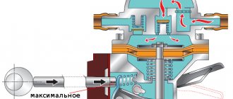
Controls the functions of the fuel pressure regulator. As a rule, a VAZ is equipped with a mechanical type device that is not interfaced with an ECU. Consequently, the failure is not detected by the system. In this case, problems usually arise:
In 2115 it is installed on the ramp and is connected by a fuel return to the gas tank, and a hose to the air inlet manifold. The serviceability of this sensor can be determined using a pressure gauge connected directly to the fuel rail. Normally at idle the readings should be:
Low pressure often also indicates that the fuel pump is faulty. At the same time, a high level indicates a free flow of fuel from the line back into the tank.
If the RTD fails, the following malfunctions are observed:
The failure of this sensor manifests itself:
The easiest way to determine its malfunction is to replace it with a known working device.
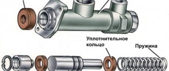
Fuel level sensor
Indicates the remaining amount of fuel in the tank. Installed directly in the tank on the fuel pump glass. It fails when the graphite contacts on the electrical board are rubbed. When replacing, you should pay attention to its type number, which is indicated on the board, since all types of FLS have different resistance. If an unsuitable sensor is installed, large errors in readings may occur.
Signs of malfunction:
- Incorrect readings about the presence of fuel in the tank;
Knock sensor
Responsible for capturing noise from the engine and transmitting readings to the ECU. The principle of operation of a piezo element is reminiscent. When detonation occurs in the internal combustion engine, it generates a small voltage and transmits readings to the head engine control unit, thereby adjusting the fuel mixture. Installed on the cylinder block between the two middle cylinders.
Signs of malfunction:
- Clattering of fingers under load;
- Increased consumption;
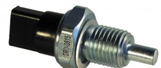
Reverse sensor VAZ 2115
The only function of the reverse sensor is to turn on the rear white lights when the driver is backing up. The signal sent by the sensor to the white lights informs other road users that the driver is moving backwards or has already started moving and is moving in reverse. And in the dark, for your convenience, these white lights illuminate the way back, informing others of your intentions.
It cannot be said that the VAZ 2114 is a very modern car filled with electronics. However, the list of sensors used that are connected to the electronic control unit is quite impressive on the fourteenth.
Each of these devices is responsible for certain functions and collects data transmitted to the main computer of the car. This way, the ECU controls the entire process and makes appropriate changes, so that the driver does not have to look for the reasons for the failure or insufficiently efficient operation of a particular unit.
Coolant temperature sensor
It is installed in the thermostat housing and is responsible for automatically turning the cooling fan on and off. The sensor is also responsible for adjusting the fuel mixture during a cold start; this can be noticed when starting the car in cold weather, with increased idle speed.
Signs of malfunction:
- The fan does not work;
- There are no warm-up speeds;
Oil pressure sensor
Oil pressure is an important indicator in engine operation; if it is absent, the internal combustion engine will not be lubricated, which will lead to engine failure. This sensor informs the driver about the presence or absence of pressure in the internal combustion engine lubrication system. The sensor is installed on the cylinder head housing and is mechanical.
Signs of malfunction:
- No oil pressure;
- The oil pressure indicator does not light up;
Video on the topic
The first injection engines, the 14th, were released in 2000-2001. After their appearance, everyone actively began converting to a carburetor system, saying “it’s more reliable,” and the number of injector specialists could be counted on one hand.
Now this situation is observed with the conversion of the electronic gas pedal into a cable pedal.
But it is worth noting that some specialists have already learned how to configure and flash e-gas, carry out rollback of a turbo engine, compressor, not to mention the evil shafts.
As for the sensors, they all serve to structure the operation of the motor.