December 23, 2015 Lada.Online 1 086 137 115
Modern AVTOVAZ SUVs use injection power units. If a malfunction is detected in the electrical equipment of the car, you should first check the serviceability of the fuses and relays. Next, we will show where the mounting block is located (fuse box or black box), as well as the location of the elements inside it.
Relays and fuses Lada 4×4 (VAZ 21214, 21314)
Modern AvtoVAZ SUVs use injection power units. If a malfunction is detected in the electrical equipment of the car, you should first check the serviceability of the fuses and relays. Next, we will show where the mounting block is located (fuse box or black box), as well as the location of the elements inside it.
Useful video
Due to the fact that the switches are of the same type, during emergency repairs the output circuit can be connected to other units. To do this, you will have to disable one of the auxiliary and non-critically important elements. For example, transfer the starter or healing circuit to the rear window heating controller.
Relays and fuses VAZ 21214, 21314 (Niva 4x4 injector)
Modern AvtoVAZ SUVs use injection power units. In the event of a malfunction in the vehicle's electrical equipment, first check the serviceability of the fuses and relays. We will then show where the mounting block (fuse box or black box) is located, as well as the location of the elements inside it.
Location of fuse and relay blocks Lada 4×4
The main part of the fuses is located in the interior of the Lada 4×4 under the panel to the left of the steering column. Total 4 blocks:
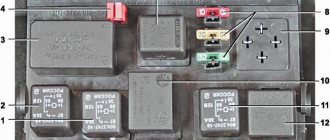
1 – engine control system fuse block; 2 – windshield wiper relay; 3 – fuse blocks; 4 – engine control system relay block.
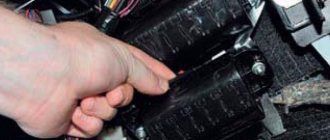
The fourth relay block is located above the gas pedal.
Main and additional fuse blocks
These two blocks are connected to each other. There are 10 fuses in the upper block, and 6 in the lower one. Markings from left to right:
Heater fan, rear window defroster, rear wiper and washer system, windshield washer pump
Steering column switch, windshield wipers, hazard warning lights, breaker relay (in turn signal mode), reverse light, instrument cluster (coolant temperature gauge, fuel level gauge, tachometer, warning lights: turn indicators, differential lock, parking brake, emergency condition of the working brake system, insufficient oil pressure, fuel reserve, battery charge)
Left headlight (high beam), high beam indicator lamp
Right headlight (high beam)
Left headlight (low beam)
Right headlight (low beam)
Side light lamps in the left front and left rear lights, license plate lights, side light indicator lamp
Side light lamps in the right front and right rear lamps, backlight lamps for the instrument cluster, cigarette lighter, switches, heating and ventilation control unit
Hazard switch, breaker relay (in hazard mode), heated tailgate glass relay contacts
Sound signal, interior lamps, brake lamps in the rear lights
Fog light relay contacts in rear lights
| F11 (8A) | Turn signal lamps and relay-breaker for turn signals and hazard warning lights (in hazard warning mode) |
| F12 (8A) | Daytime running light relay, daytime running light bulbs |
| F13 (8A) | Rear Fog Lamps and Relays |
| F14 (16A) | Cigarette lighter |
| F15 (16A) | Spare |
| F16 (8A) | Spare |
Additional fuse circuits in the Urban package:
Fuse number and rating
Electric windows for front doors Electric side mirrors
Air conditioning fan, air conditioning compressor
Side mirror heaters
Central interior lamp
Air conditioning fan, air conditioning compressor
Fuse box Niva Chevrolet
Cars considered were 2002, 2003, 2004, 2005, 2006, 2007, 2008, 2009, 2010, 2011, 2012, 2013, 2014
Where is the fuse and relay mounting block located?
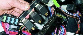
Most fuses and relays are located in the mounting block under the instrument panel on the left side.
To get there you need to unscrew two screws with a screwdriver.
By pressing the top edge of the cover, we remove it from engagement with the instrument panel
Next, moving the cover up, remove the cover pins from the rubber bushings and remove the cover
behind the cover is the fuse box
Decoding for cars from 2009
Mounting block fuses in the Chevy interior
Fuse designation (rated current, A)
License plate lights, side light lamps in the left headlight and left rear light, engine compartment lamp, side light indicator lamp
Low beam lamp (left headlight)
High beam lamp (left headlight), high beam indicator lamp
Left fog lamp
Power window relay, front power windows
Horn Relay, Horn, Trunk Lamp
Heated tailgate glass element, heated tailgate glass relay, heated outside rear view mirror elements
Heated tailgate switch, windshield wiper relay, windshield wiper motor, windshield washer pump, right steering column switch, glove compartment lamp, reverse lamps
Remote control unit for electrical accessories (door locking)
Side light lamps in the right headlight and right rear lamp, instrument lighting brightness control
Low beam lamp (right headlight), gear motors for headlight beam control
High beam lamp (right headlight)
Right fog lamp
Outside mirror control unit, electric outside rear view mirrors, heated seat control unit
Relay-breaker for direction indicators and hazard warning lights (in hazard warning mode)
Interior lamps, anti-theft system status warning lamp, brake lights, additional brake light
Heater fan, heater fuse
Relay-interrupter for direction indicators and hazard warning lights (in turn signal mode), instrument cluster (except for engine management system malfunction warning lamp), starter relay
Fog lamps in the rear lights, anti-theft control unit, buzzer
Relay of the mounting block in the car interior
K1 (not used)
Windshield wiper relay
Windshield wiper motor
Relay-breaker for direction indicators and hazard warning lights
Turn signal lamps
Low beam relay
Low beam headlight bulbs
High beam relay
High beam lamps for headlights
Tailgate heated relay coil, heater fan, windshield wiper and washer, tailgate wiper and washer
Heated tailgate glass relay
Tailgate glass heating element
Remote relays are attached to the bottom of the mounting block
1 — fog lamp relay; 2 — power window relay; 3 — seat heating relay; 4 — sound signal relay; 5 - starter relay
Fuse and relay block for Chevrolet Niva up to 2009
Remote relays
Chevrolet Niva engine management system fuse and relay block.
Where is it located?
Attached to the controller bracket.
To get to the fuses and relays, you need to remove the glove box.
Click on the image to enlarge
Location of relays and fuses in the Chevrolet Niva block
1 - additional relay (turns on the right electric fan through an additional resistor at low rotation speed); 2 - fuse (50A), protecting the power circuits of the additional relay and the right electric fan relay; 3 - fuel pump (fuel pump) fuse (15A), protecting the power circuits of the electric fuel pump relay; 4 - fuse (15A) protecting the constant power supply circuit of the controller; 5 — right electric fan relay; 6 — left electric fan relay; 7 — electric fuel pump relay; 8 - main relay; 9 - fuse (50A), protecting the circuits of the left electric fan; 10 - fuse (15A), protecting the power circuits switched on by the main relay; 11 - controller
To replace the fuse and relay, remove it from the block, you can pry it off with a screwdriver.
To replace the relay and fuse for the air conditioner, remove the left screen of the instrument console
We remove the relay by hand. Install new fuses and relays in reverse order
Chevrolet Niva fuse diagram
How to remove the relay and fuse mounting block
Remove the block cover, then use a Phillips screwdriver to unscrew the self-tapping screw securing the mounting block
We remove the block holders from the bracket and disconnect the five wires of the instrument panel harnesses from the block
Pressing the latches of the remote relay pads
and sliding it off the block guides, remove the pads assembled from the relay, similarly remove the remaining pads
Removing the mounting block
Installing the unit in reverse order
Engine control system fuses
It is located on the left side of the body, under the instrument panel, next to the diagnostic block. Consists of four fuses:
| F1 (30A) | Right electric fan relay contacts |
| F2 (30A) | Left electric fan relay contacts |
| F3 (15A) | Relay windings of the right and left electric fans, controller, injectors, ignition coil |
| F4 (15A) | Heating elements for control and diagnostic oxygen concentration sensors, phase sensor, mass air flow sensor, canister purge valve |
Engine Control Relay Box
Below the main and additional fuse blocks there is a relay block for the engine management system, which consists of five relays and one fuse:
| №1 | Ignition relay |
| №2 | Main relay |
| №3 | Right cooling fan relay |
| №4 | Left cooling fan relay |
| №5 | Fuel pump relay (fuel) |
| №6 | Fuel pump fuse F5, 15A |
On some vehicle versions, a starter relay may be located under the additional unit next to the ignition relay.
Relay block diagram above the gas pedal
| №1 | Rear fog lamp relay |
| №2 | Rear window heating relay |
| №3 | Low beam relay |
| №4 | High beam relay |
Mounting blocks for Lada 4×4 2021
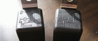
The turn signal relay (part number 8450082700, 9-pin), as well as the windshield wiper relay, are located under the trim in the driver’s feet, to the left of the fuse mounting block.
Attention!
The relay and fuse diagram may differ depending on the configuration and production date of the vehicle. Current diagrams of the mounting block are presented in the operating manual for the date of manufacture of the car (download from the official website for 3-door or 5-door).
Why does a fuse or light relay or any other constantly blow out? Before replacing it with a similar one, you must first find and eliminate the cause of its burnout. This could be a short circuit, incorrectly selected rated current, etc. Use electrical circuit diagrams to troubleshoot problems. Questions on this topic can be asked on the forum.
Troubleshooting wires
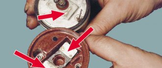
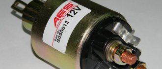
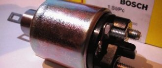
During operation of the power unit starting device, the entire load is transferred to its solenoid relay. Therefore, to the question: why does the starter click, we can answer that the relay begins to function, making characteristic sounds. This indicates a malfunction, since the starter does not work at this moment and does not turn the crankshaft of the car engine. The occurrence of such symptoms is typical for the following situations:
- short circuit or burning of the turns of the rotor or stator windings;
- deterioration of the bushings, which caused the motor shaft to jam;
- breakdown of the rotor to ground.
Without removing the device from the car and completely disassembling it, it will not be possible to detect such malfunctions.
The traction clicks due to the fact that its core moves between the retracting and fixing windings, and if the voltage on the latter is insufficient, it cannot hold on and returns to its original position. The presence of clicks is evidence of unsuccessful attempts by the core to stay in the required position.
Note that if it was not possible to start the vehicle engine the first time, this is not at all evidence of a faulty starter. It is likely that most systems have not yet started working; to do this, you need to turn the ignition key again.
In addition to the solenoid relay, burnt contacts (this is accompanied by a characteristic burning smell and, in some cases, smoke), lack of ground, disruption of the integrity of the electrical network, or a discharged power source can cause problems with the engine starting system. Elimination of these faults is carried out on an individual basis.
Some drivers, in search of a malfunction, are in a hurry to remove the starter, but such hasty actions should not be taken, since often the problem of the engine not starting is due to wires, poor contacts or their absence. Here are the most typical defects:
- low weight of the engine and body;
- unreliable connection of the starter wires (plus of the rotor winding, main plus, power supply contact from the ignition switch to the solenoid relay (SR)).
Also interesting: Transfer case seals Niva Chevrolet in Balashikha
