Malfunctions and replacement of the VAZ 2110 throttle position sensor The VAZ 2110 throttle position sensor (TPS) is an automobile potentiometer that transmits data to the regulator about how the throttle is positioned. The latter can change its location depending on the intensity of pressure on the gas pedal. There is a voltage regulator at the base of this device.
Its readings are recorded by the controller and, taking into account the available information, it supplies gasoline in portions. If it breaks down, the controller will receive distorted information. This can lead to suspension of its operation and excessive fuel consumption.
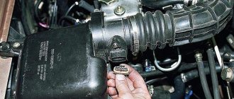
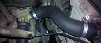
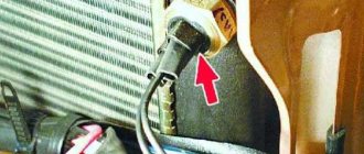
As a result of the signal pulse from the TPS, the controlling sensor evaluates the current throttle position, and the intensity of the signal change analyzes the degree of pressure on the accelerator pedal. This becomes a decisive circumstance for activating the necessary modes, as well as directing the air flow past the throttle through the idle shut-off and control mechanism. The TPS in a VAZ car is located in the engine compartment on the throttle fitting. It connects to the damper shaft.
Symptoms of sensor malfunction
The main control unit contains a program: if one of the important meters stops working, the air-fuel mixture is prepared and supplied according to average indicators, and the Check Engine warning sign turns on on the dashboard. Emergency operation with increased fuel consumption is a clear sign of a breakdown of any sensor.
The insidiousness of the TPS is that it does not break in the usual sense. When the resistive film begins to wear away, the resistance of the device changes unpredictably. The controller either “sees” a working sensor in the circuit, or notes incorrect voltage surges and tries to switch to emergency mode. From here, the main sign of a malfunctioning throttle valve is determined - a periodically flashing Check Engine display.
The problem is accompanied by a change in the behavior of the engine, or more precisely:
- “shaking” and spontaneous stops of the engine idling;
- there is no acceleration dynamics; after pressing the gas pedal, jerks and dips are observed;
- increased idle speed of the power unit (1500–2500 rpm);
- the car “does not pull” due to loss of power;
- jerks are also felt while driving;
- Fuel consumption increases by 10–25%!
The listed symptoms can be caused by a dozen reasons, ranging from malfunctions of the ignition system to wear and tear of engine parts. That is why it is important to weed out problems that lie on the surface, including incorrect operation of the throttle position sensor.
What are the causes and signs of TPS failures on Lanos?
If you suspect a malfunction of the TPS, then the first thing you need to look for is the presence of a number of the following symptoms:
- Reduced engine power
- Increased fuel consumption
- Delayed engine response to pressing the accelerator pedal
- Jerking occurs when accelerating hard
- Problems starting the engine
- The “Check Engine” indicator lights up, indicating an engine error.
The described symptoms do not indicate 100% that the cause of the malfunction is the damper sensor. That is why it is additionally recommended to check the device. Absolutely every driver can perform a TPS check on Lanos, and for this it is not at all necessary to visit a car service center. How to check the damper sensor on Lanos, we will find out in detail.
Malfunctions
There are several telltale signs of trouble that may indicate that there is a problem with the throttle valve control.
- High idle speed;
- When the gear is switched off, the engine may stall;
- When the car picks up speed, the car jerks and jerks are felt;
- Acceleration dynamics deteriorate significantly;
- Floating speed occurs at idle.
It should be noted that similar symptoms may also be characteristic of the failure of other components - the idle speed control or the ignition module, for example. Therefore, you first need to check the TPS.
Checking the status of the regulator
Next, let's talk about how you can check this throttle valve sensor. The event is necessary because it allows you to understand whether all the troubles are really due to it, or whether the problems arose due to the failure of other elements of your car.
We recommend: Removing the radiator grill on Renault Duster: two methods + video
It’s not uncommon for novice car owners to make hasty conclusions based on the primary signs of a breakdown. This results in unnecessary repair work and costs.
To check the current status of the throttle position sensor you need to:
- Measure the voltage at the output of the slider, turning on the ignition and opening the idle contacts;
- If the test shows that the voltage is more than 0.7 volts, then the sensor has indeed failed;
- Open the damper completely. In normal condition, voltage readings should be no more than 4 volts;
- Measure the variable resistor for resistance;
- To do this, connect an ohmmeter or a multimeter in ohmmeter mode to the power supply and output;
- Slowly begin to turn the throttle;
- At the same time, monitor the readings on the device;
- If, as the damper opens, the resistance also changes slowly, then the unit is working properly.
If you find during the test that the sensor is faulty, you only need to replace it. It cannot be repaired.
The resistive layer along which the slider moves wears off over time due to friction. Because of this, the regulator begins to produce incorrect data, the characteristics of the supplied mixture change, and engine performance deteriorates.
Disabling the regulator
Type of damper sensors
Manufacturers produce two types of devices in question. Both options are used on Lanos, so let’s look at their features. There are film-resistor and non-contact throttle position sensors. They differ in design and operating principle.
A film-resistor TPS or contact one consists of tracks that are variable resistance.
The element is based on a movable slider, when moved, the resistance increases. The sensor design has three contacts - plus, ground and engine control. The device is supplied with a constant voltage of 5V.
A non-contact TPS or magnetoresistive on Lanos is a potentiometer that works on the principle of changing the influence of a magnetic field.
The design of the element contains a permanent magnet, and changes in the position of the damper are recorded using an electronic unit. A distinctive feature of contactless devices is their durability. Such devices are more expensive than contact devices.
TPS problems and their diagnosis
As you know, eternal parts for cars have not yet been invented. And the breakdown of the TPS can be foreseen; for this you need to inquire about the possible reasons for the failure of this part. Here are the main ones:
- Abrasion of the sprayed base layer, which serves to move the slider (the result is incorrect TPS readings).
- Failure of the movable type core (the result is deterioration of the contacts between the slider and the resistive layer).
How can you figure out problems with this sensor yourself? To do this, you can independently diagnose the operation of your diagnostics:
- Listen to the VAZ-2110 engine idling:
- the breakdown is obvious if you notice that its speed is in a “floating” state;
- Quickly release the gas pedal:
- a malfunction is present if the engine stops after this action.
- Pick up speed:
- There is a problem with the TPS if the car starts to move jerkily, which indicates an incorrect supply of fuel to the system.
Experts say that most often the sensor fails when the resistive track is heavily contaminated or is completely broken. To verify the opposite, you need to check the working condition of the TPS.
Typical TPS problems
A malfunction of the throttle sensor can be determined by the following symptoms:
- increase in speed intensity when the load is off;
- deterioration of dynamic performance;
- the appearance of jerks when picking up speed;
- sudden stopping of the engine in neutral;
- warning light with a light bulb.
In addition, there are other malfunctions. One of the most common is a decrease in the base coating thickness in the initial part of the slider stroke. This prevents the linear voltage level of the output signal from increasing. Another causal relationship may lie in the failure of the movable core. The breakage of one tip contributes to the appearance of a large number of burrs at the base. As a result, others also break, causing the slider to lose contact with the resistive part.
You can test the throttle sensor yourself by following these steps. The first step is to start the ignition; if the warning light does not light up, then we take the converter directly. Using a multimeter, you should measure the potential difference between “−” and the slider wire. The obtained parameters should not be higher than 0.7 V.
We recommend: Permissible tread height for a new summer tire
Next, you need to expand the sector to fully open the damper. Then you should recheck the voltage again. The readings must be at least 4 V. After this, you need to turn on the ignition and remove the connector. Again measure the resistance at the point of contact of the slider with one of the terminals. While scrolling the sector, monitor the multimeter readings.
The pointer should be moved gently and slowly, since shocks and sudden vibrations indicate a breakdown. The smooth operation of the device depends on the condition of the film resistor.
There are several types of throttle position sensor: film-resistive and non-contact. The first of them is installed by the manufacturer, the second is chosen by the car owner while driving and operating the car. The service life of the TPS may vary depending on the quality and adherence to technology in the manufacture of the device. The standard unit may not need to be changed even for 60,000 km, and sometimes it requires replacement even after 5,000 km.
When purchasing a throttle sensor, the price depends on the choice of its type:
- Film-resistive ones are the most frequently purchased among motorists due to their budget price, but their service life practically does not stand up to criticism;
- Contactless - at a higher cost (almost twice) the long period of use covers all costs. The high-quality operation of the device is due to the principle of magnetoresistance. When purchasing, you should be aware that this type of device operates at a DC voltage proportional to the throttle valve opening angle in the electric motor fuel injection system.
The sensor shaft rotates clockwise from the damper side. The service life guarantee is 3 years. Drivers do not repair the resistive sensor, but replace it with a contactless one - it is undoubtedly more reliable. Its design includes a rotor and a stator. The rotor is not affected by the magnetic field, because there is a magnet at its base. The stator is a part that is quite sensitive to the electromagnetic field. Its assembly is associated with programming, so a device of this category is often used for installation in electrical control units.
DPDZ area of responsibility
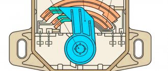
In this article we will look at the features of this part and provide detailed instructions for its repair, adjustment and replacement. But before moving directly to the practical part, you should pay a little attention to theory and consider what the throttle valve and its sensor are, what functions they perform and where they are located. So, the damper itself is a structural component of the engine intake system. Its functions include adjusting the amount of incoming air, i.e. it is responsible for the quality of the fuel-air mixture.
The throttle position sensor provides information to the manifold about the state of the bypass valve. This is obvious from its name. The sensor can be film or non-contact (magnetic). Its design is similar to an air valve, and when it is open, the pressure in the system is equal to atmospheric pressure. But as soon as the element moves to the closed position, the value of the above characteristic immediately decreases to a vacuum state.
Throttle position sensor
The throttle sensor consists of constant and variable resistors, the resistance of which reaches 8 ohms. The voltage at its output, depending on the position of the damper itself, constantly changes. The entire process is monitored by a controller, and the amount of fuel is adjusted depending on the data received. If the TPS does not work correctly and produces distorted data, then not enough fuel will enter the system or there will be an excess of it, which will lead to disruption of the engine and even sometimes its failure. In addition, the correct operation of the gearbox and ignition timing depend on this device. We will not calculate how much it will cost to repair these mechanisms.
To diagnose any unit or part, you need to know its location. The throttle position sensor is located in the engine compartment. You can get to it after you find the throttle pipe, on which the TPS is fixed.
Location and principle of operation of the meter
The sensor is installed on the throttle valve block and is mechanically connected to its axis. Thanks to this, the device is able to solve 3 problems:
- inform the controller at what angle the throttle is currently open;
- signal that the air supply is completely closed (the driver has released the accelerator pedal);
- monitor the speed at which the damper opens.
Based on this information, the electronic powertrain control unit (ECU) makes a decision to increase or decrease the fuel supply and fuel injection for intense acceleration when the gas pedal is sharply pressed.
Reference. Two types of TPS are installed on cars: resistive and non-contact. The first ones are cheaper and therefore are found on all budget cars. The latter are more reliable and more expensive, and are installed on cars of medium and high price categories.
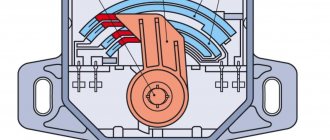
The operating algorithm of the resistive sensor is as follows:
- At idle, the damper is closed and air flows into the engine through a separate channel. The voltage at the output of the device does not exceed 0.5 volts; the controller supplies fuel to maintain engine idle speed.
- When the driver presses the gas pedal, the sensor slider moves along the resistive film. The resistance of the electrical circuit into which the device is connected in series decreases.
- The ECU “sees” the increase in voltage in the meter circuit, makes a calculation, prepares the air-fuel mixture in the required quantity and supplies it to the cylinders. The maximum voltage at wide open throttle is about 4.5 V.
- When the driver sharply presses the accelerator pedal, the controller notes a similar voltage surge and delivers a portion of the enriched mixture for dynamic acceleration.
Note. The operating voltage values are indicated for a common Russian car - VAZ 2110.
The non-contact throttle position sensor functions identically. The difference lies in the method of influencing the electrical circuit. A resistive device changes resistance using a slider moving across the film, while a non-contact device changes resistance due to the magnetic-resistive effect. Thanks to this principle of operation, the TPS lasts much longer and does not create problems for the owner of the car.
We recommend: How to properly bleed the brakes on a VAZ-2114?
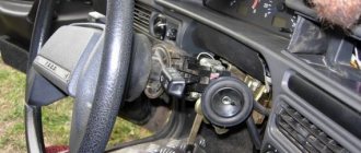
Adjusting the TPS or how to adjust the damper position sensor with your own hands
After installing a new TPS on Lanos, it is necessary to adjust the device. Setting (also called calibration) is needed to ensure the correct functioning of the element. The adjustment features are based on the following steps:
- First, we check the element and make sure that it needs adjustment. To do this, we measure the voltage at the sensor contacts. The value should be 0.7V with the damper closed. If this is not the case, then the TPS needs adjustment
- To do this, loosen the fastening screws and turn it clockwise. If there is no free play when loosening the screws, then you need to increase the diameters of the sensor holes. This can be done with a file or a drill bit.
- Having enlarged the mounting hole, you need to reinstall the element in place and measure the voltage with the ignition on. The value should be 0.65-0.7V
- Having set the appropriate voltage value, it is recommended to reset the ECU by removing the negative terminal for 15-20 minutes
- After connecting the terminal, you need to turn on the ignition for 15 seconds and then turn it off
- The ignition is turned on again and the engine starts
Now you understand what adjusting the TPS on Lanos is, and why you need to perform this procedure. After installing a contactless throttle sensor, you can notice improvements in your car such as improved engine responsiveness when you press the gas pedal, the disappearance of twitching and jerking in 1st and 3rd gear, reduced fuel consumption, etc. Reviews show that it is better to overpay and buy a contactless damper position sensor than to replace contact devices every 2-3 years.
Why is it needed?
The throttle position sensor is responsible for determining the current throttle position. Depending on this, the fuel supply system changes the amount of fuel supplied under one or another operating mode of the power unit.
If problems arise with it, you can contact a service station so as not to waste your energy and nerves. But in practice, changing the TPS yourself is quite simple, plus you will save a decent amount of money.
The desired regulator is located on the side of the throttle pipe on the throttle valve axis.
Regulator location
Features of work
The TPS is essentially a variable resistor, one output of which is supplied with 5 Volt power. The second contact is connected to ground, and the third is connected to the controller.
When you press the gas pedal, the voltage changes. The sensor monitors the output voltage on the controller, thereby regulating and monitoring the quality of the supplied air-fuel mixture. This directly depends on the opening angle of the damper itself.
If for some reason this regulator fails, a catastrophe will not occur, since another sensor, the mass air flow sensor, will temporarily take over its functions.
This does not mean at all that the TPS can not be changed. Each regulator has its own functions, so there is no point in transferring the tasks of the TPS to the MAF.
How to replace the throttle position sensor on a Chevrolet and Daewoo Lanos
If diagnostics show that the TPS on Lanos is faulty, then it should be replaced. There are no difficulties with the replacement, but we will consider this process step by step. Before removing the old sensor, you need to remove the terminal from the battery. This is done in order to prevent the occurrence of a short circuit, as well as to reset the ECU error
. If this is not done, then after replacing the TPS, you may find that the Check Engine will light up on the instrument panel.
Instructions for replacing TPS on Lanos are as follows:
- After removing the negative terminal from the ECU, you should disconnect the chip with the power wire by prying the clamp with your fingers
- Unscrew the bolts securing the device and remove the part from the car
- Install a new one in place of the old sensor and secure it with bolts. Connect the chip with wires
The replacement instructions are not difficult, but it is important to know some nuances:
- Lanos produces different types of sensors, which have corresponding article numbers or catalog numbers. The table below shows device part numbers for cars with different types of 1.4/1.5/1.6 liter engines
- It is necessary to configure the TPS, which is described in detail in the next section
- Mounting form - it is important to pay attention to the type of holder or damper axis. They are different, so before purchasing it is better to remove the sensor and see what type of mount is used on it
The table shows that Chevrolet and Daewoo Lanos with engine sizes of 1.5 and 1.6 liters use devices with article number 3102.3855. Lanos with 1.4 engines, as well as Sens, use elements with catalog numbers 3202.3855 and 3302.3855.
This is interesting!
It is recommended to install contactless sensors, as they not only last longer, but also work much better.
Checking the operation of the throttle position sensor
To check the TPS yourself, it is not necessary to call an auto electrician for consultation. To do this you need a multimeter or voltmeter. Next, experts offer step-by-step instructions for checking the sensor.
The first step is to turn the key in the ignition switch, take the voltage readings between the sensor slider contact and the minus. In normal condition, the indicator will be up to 0.7 V.
The second step is to turn the plastic sector and open the damper, and then take measurements again. In the normal state of the sensor, the device will show a result of 4 V.
Installation of TPS on mono-injection, ABS engine
FAQ VW Audi Skoda Seat
The ABS engine was installed on the following cars:
Volkswagen Passat B4 / Volkswagen Passat B4 (3A2) 1994 - 1997 Volkswagen Passat Variant B4 / Volkswagen Passat Variant B4 (3A5) 1994 - 1997
Volkswagen Passat B3 / Volkswagen Passat B3 (312) 1988 - 1994 Volkswagen Passat Variant B3 / Volkswagen Passat Variant B3 (315) 1988 - 1994
Volkswagen Golf 3 / Volkswagen Golf 3 (1H1, 1H5) 1992 - 1998 Volkswagen Vento / Volkswagen Vento (1H2) 1992 - 1998 Volkswagen Golf Cabriolet 3 / Volkswagen Golf Cabriolet 3 (1E7) 1993 - 2002
SEAT Ibiza 2 / Seat Ibiza 2 (6K1) 1993 - 2002
SEAT Cordoba / Seat Cordoba (6K2) 1993 - 2002
SEAT Toledo / Seat Toledo (1L) 1991 - 1999
The information applies to the repair of vehicles with Mono motronic injection system
Hi all! So I decided to write how to install the TPS (throttle position sensor) on a single injection! Because Topics on this issue often come up, but there is still no general topic where everything is discussed!
Let's start, for this you will need the following tool: 1. A digital tester, preferably 2. A set of thorax 3. Alcohol 4. Cotton swabs 5. Analog tester (arrow) 6. An oscilloscope, preferably 7. A strobe (in my case Iskra1 from the 80s)
Problems associated with the TPS: Dips when starting, at low positions of the DZ (I had a 9-11*), failures in engine operation until the internal combustion engine (internal combustion engine) stops, slightly increased fuel consumption (by about 1 liter), insufficient dynamics during adaptation The DZ potentiometer error popped up (unfortunately I don’t remember the number), when warming up, especially in the cold season (temperature -5* and more), the effect of floating was observed (not even floating, but it was accelerating itself, as if someone had given the gas and released it), at the end, when the TPS had already died, the unstable idle speed and frequent stops of the internal combustion engine, especially on a cold engine. I would like to make a reservation right away that this is all true only in the case when everything else in the engine and electronics of the car is in good working order and adjusted (timing timing marks, ignition is set, lambda probe (oxygen sensor) is 100% live and its mileage is no more than 100t.km, DTOZh is working and the temperature resistance corresponds to the characteristic, the IAC is working, the spark plugs, explosive wires, the slider and the distributor cover are working, and all consumables have been replaced). Otherwise, you can disassemble a serviceable and innocent TPS!
A simple way, disassemble, clean and reassemble for those who read first and then do!
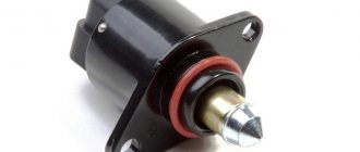
First we warm up the car to 90*. To measure the initial voltage 0* DZ, for this you need to push the IAC rod all the way, this can be done in three ways:
1. Remove the connector from it and apply voltage to the top 2 contacts (for a 4-pin IAC) with such polarity that its rod slides in all the way. It is advisable to supply voltage from a 6V battery; if there is no 6V source, you can supply 12V, but through a 12V 5W light bulb, it will act as a limiting resistance so as not to break the IAC gearbox. This is done with the ignition off.
2. If you are alone and there is no 6V source, turn on the ignition, approach the engine from the right side (in the direction of travel), with one hand open the remote control enough so that you can press the IAC limit switch, at this moment the IAC will move in (press the limit switch with the same hand, which we open the remote control) and then moves out a little, so you need to catch the moment when it has moved in, but has not yet had time to move out and disconnect the connector (with the other hand) from it, if it didn’t work the first time. Let's try again, I managed to do this the first and second time!
3.Unscrew the 3 bolts under the thorax and remove the IAC.
The IAC rod has been removed, now you need to check whether the IAC rod does not rest against the remote control, otherwise the voltage measurement will be inaccurate. How to check the gap and adjust it after cleaning is described here.
Everything is ready to measure the voltage, the ignition should be on, take a digital tester and measure the voltage between the 1st and 2nd legs of the TPS (contacts are counted from right to left, contact 3 is missing), while opening and closing the DZ several times to more accurately measure the voltage perhaps it will not always be the same, then we look for the arithmetic mean, but it should still be very close to the voltage 0.18-0.2V + - 0.2V, if this is not the case, then this method, unfortunately, is not suitable for you because your TPS is very worn out and adjustments will have to be made using the second method using a computer and other means! Measure it and write it down on a piece of paper, otherwise you’ll easily forget the value while you’re cleaning it.
Now we remove the mono injection from the car. On the radio, how to remove the mono-injection: remove the corrugation from the air filter to the mono-injection, 2 clamps, disconnect the 2 hoses at the back of the mono-injection to the thicker absorber to the thinner hot-cold air damper (be careful with the plastic fittings), unscrew the volute 3 10mm wrench bolts, disconnect the throttle cable , disconnect all the wiring from the mono-injection (injector, IAC, TPS, heating the hedgehog), remove the heating wire for the hedgehog from the holder of the mono-injection, disconnect the fuel hoses, be sure to plug the 2 clamp holes so that no dirt gets in, unscrew the 4 turnkey bolts for the 10th spacer of the mono-injection, mono injection in your hands!
Now you need to measure the resistance of the tracks between different contacts as in the table and write down all the values on a piece of paper so that you can then compare them with those that will be after reading the TPS
Table 1
The values for the majority of those measured are indicated in parentheses.
If your values are higher than the maximum permissible values, then your machine could not work normally, which means you are going in the right direction. I changed mine to a new TPS, on the new one the values were all at the minimum values. My old TPS had a resistance (1+4) of 8 kOhm, although after cleaning everything returned to normal, I extended the life of my potentiometer by 1 year until it completely died.
Now how to check the TPS with an oscilloscope. I think this is the most reliable way to check for a malfunction of the TPS, although I haven’t used it myself (even though I have it, I was sure that it was the problem) We set the volt/division switch to such a limit that the 5V voltage swing is more than one cell and full screen. We check on a car with the IAC retracted and the ignition on, connect the ground wire to 1 paw of the TPS signal to 2 and try to open the DS voltage should change in the first half of the DS opening, without jumps and bursts (contact bounce effect) smoothly and always with a smooth opening of the DS should only grow, falling is unacceptable in the first half!!! In the second half of the DZ stroke, a slight drop and increase is possible, but the voltage should not disappear under any conditions. Then we measure the voltage between the 1st and 4th contacts, also on the 1st ground on the 4th signal, in the first half of the opening of the remote control, the voltage may move up and down a little, but not disappear!!! In the second half, the DZ should also increase smoothly without jerks; at the very end of the DZ stroke, a slight voltage drop may occur. If after measurements with an oscilloscope nothing suspicious was detected, you should not open the TPS at all! I would also like to say that I did not have problems while driving immediately, but after some mileage (several km), i.e. when the mono injection was warming up, so it’s worth driving the car before taking all measurements. No matter how I tried to catch the failure of the TPS characteristic with testers, I was never able to do it, neither digital nor analog, apparently they have a large inertia, as I already said, the failure of the characteristic was clearly visible with a miniscanner that is being developed on our forum, here. When driving a car with a microtester, it was clear (but the truth is not always) that you give a little gas, and the throttle angle begins not to increase, but for some reason to fall, and sometimes even dropped to zero while the car was “nodding off.” I couldn’t catch it with the tester, everything was smooth!
Let's start removing the TPS, unscrew the 4 bolts under the thorax, pay attention to your tool, the thorax must have a hole inside it, otherwise you won't be able to unscrew it!!!
Or we carefully unscrew the TPS in place, I’ll tell you right away it’s not very convenient, and the condition of the sliders will be hard to see.
We open the TPS; it sits on the DZ axis and has a seal in the form of a rubber ring, carefully slide it along the edges and remove it, shaking it along the DZ axis! Let's look at what's inside, there are still sliders on the remote control axis. We inspect their condition, they must be in perfect condition. My top one felt like it was burnt, if suddenly we also take some sandpaper from you (preferably 2000 grit) and carefully clean it so as not to bend the petals. You should not bend the sliders, this will lead to faster depletion of the resistive layer of the TPS. We look at the potentiometer itself, is the resistive layer worn? Pay attention to the contacts from the connector, is there anything suspicious there in the form of cracks or loose contacts?
If the resistive layer looks decent and is not very worn, then I advise you to simply wipe the resistive layer with alcohol and put everything back together, apparently it was not Babin’s fault! You can wipe the resistive layer with spindle oil ONLY WIPE, not pour. Or there is even a special lubricant for potentiometers. But for some reason many are against lubrication, well, it’s up to you to each their own, I think that with oil the effect of contact bounce is eliminated, as everyone probably heard on old equipment, you turn the volume and rustles and crackles, there’s like the same potentiometer, I haven’t even taken them apart before I just dripped it with oil and forgot about them forever. So, the ECU won’t like this kind of contact bounce because... Digitization goes very quickly and imagine what the ECU thinks from such voltage surges!? That's right, it's not good that problems with XX begin in the first place.
If, after all, the resistive layer is very worn out, and even more so the substrate is already visible (as in the photo above), then some actions need to be taken, then simply cleaning will not help here! As I understand it, it’s usually the top track that gets worn out. There are 2 ways to treat. 1. As I did, but it’s not entirely successful because you have to be very careful and you need to understand what to bend and fold where. I had worn out the top path and I had to essentially move just one slider to a layer that was not yet working. I used a thin needle to carefully bend several petals of the slider, one up and the other down, while making sure that the slider itself remained at the same distance as the others. protrusion to the resistive layer. This kind of repair lasted me a year, although as you can see in the photo, the wear on my TPS is very large and it was already like that when I first opened it, maybe quite a bit less. After this, we do with the coating of the resistive layer what was mentioned just above.
2. The method is much simpler and probably not tested more successfully, it was suggested to me by Ten70. The point is to move the entire potentiometer vertically up or down by 0.5mm, and this will achieve a shift of the sliders by 0.5mm, which is quite enough considering that one slider is about 2mm. Where to shift the potentiometer must be looked at for each potentiometer separately, where there is more of the non-working layer relative to the worn one in the opposite direction and move it. For example: wear from the sliders is visible and at the top there is a greater distance of the still untouched resistive layer, which means that in order to get to this layer the potentiometer must be lowered! Now, since the potentiometer itself sits on the remote control axis, and you can’t just lower it, it means you need to bore the bushing in the potentiometer by 1 mm in diameter so that it can move up and down relative to the axis by 0.5 mm. It is better to bore the bushing with a reamer, but if there is no reamer, you can use a drill, I will not write the data of drills and reamer, it is possible that the axes can be of different diameters. Berm calipers measure the diameter of the axis and add 1-1.1 mm, and we get the desired size of the drill or reamer. Expand (drill) the bushing, you should get something like this:
this is what it looks like after boring with a reamer
After this, we do with the coating of the resistive layer what was mentioned just above.
After this, we put the potentiometer back and tighten the bolts. In the second case, it should be noted that you must remember where to raise or lower the potentiometer and try not to move it to the right or left. Before installing a single injection on a machine, you should check the gap between the IAC limit switch and the DZ stop as described here. press We install a single injection on the car, connect only the TPS, turn on the ignition, connect the tester to pins 1 and 2 and set the previously recorded voltage, slightly tighten the TPS bolts without disconnecting the tester, open and close the DPS several times and make sure that the voltage remains the same, otherwise repeat the adjustment. Turn off the ignition and disconnect the TPS connector. We check the readings given in the tables with those we measured before and after cleaning; if somewhere we still do not fit into the limits, then the TPS must be replaced. It’s better to check with an oscilloscope as I said above, with a digital tester to track the smoothness, but the resistance values won’t work, you need, at least if you don’t have an oscilloscope, an analog tester (arrow) and use it to check the smoothness of the change in resistance according to the table, the arrow should move smoothly without jerks and dips, like described when measuring with an oscilloscope. We connect all the connectors, disconnect the battery for 10 minutes to clear the errors, connect the battery and start it, warm up the engine. Let's see if anything has changed in the operation of the engine or not. Now you need a computer to make an adaptation of the DS, otherwise the mixture may become richer or leaner according to the lambda probe, as I had after replacing the DSZ. How to do this is described here, click here.
After adaptation, if all engine systems are working properly, the lambda coefficient should float around 0.980-1.020, for me, somewhere in this area. Be sure to check XX; it must correspond to the manual of your engine, otherwise there is no point in taking measurements! Count errors, there should be no potentiometer errors; if they appear again, it means something good has not happened and can only be cured by replacement. Although I drove for some time with errors, and the car behaved normally, you will generally decide for yourself in the course of events. Then you can measure the voltage between 1 and 2 of the second contact at XX, with the power consumers turned off, if, again, all systems are working properly, the injection should be 0.7V (on mine 0.65-0.95V fluctuates a little) if it differs greatly by more than 0.5V, the fault should be looked for in another place. I read on the forum that if the voltage is too high, then it is most likely a dead lambda probe or late ignition. Don’t try to achieve 0.7 in the rotation of the TPS with the car running, no matter how much I tried to achieve an overestimation of the voltage, it didn’t work for me; at first it rises, but then the ECU corrects everything and we get back to square one. It all depends on the system as a whole; this is simply an indicator of the serviceability of the injection, nothing more. The rotation of the TPS has very little effect on the idle speed in general, but has a very strong effect on the enrichment or depletion of the mixture in lambda.
That’s all about the method when I read it and started doing it, and if I took it off and didn’t try it on, a few more points are added here.
Now about what if they removed it, but we don’t know how to install it in its place! Here, accordingly, everything related to cleaning the TPS will be omitted and in what order! In this situation, it is very difficult to identify and find out what is faulty, so I will describe what can be done and if it works, then you are in luck. Be sure to check the installation of the timing marks, set the ignition strictly according to the manual, it doesn’t matter that your car does not drive with this ignition, on the Monomotronik MA1.2.3 from the computer to install the OZ, do not forget to enter the basic settings mode, otherwise you will not set the ignition. It should not be desirable to check for errors; it is advisable that there should not be any TPS either. Check the DTOZ when the car is warm, at least so that the temperature resistance corresponds to 80 * 300-400 Ohm, 100 * 175-225 Ohm, and the lambda probe must definitely be alive; in the absence of at least one of these conditions, it will not be possible to set the TPS correctly. We set the voltage between 1 and 2 to 0.2V, warm up the car, connect the computer, and see what the probe’s lambda coefficient shows; if it is very far from these numbers 0.900-1.100, you can immediately start looking for a fault in your car that is not related to the TPS. All the following adjustments should be made with the power consumers turned off; even when the fan is turned on, there is no need to adjust anything because all the variables begin to float away!!! If it fits into these values, then we release the TPS bolts and right at XX we begin to move the TPS drop by drop and try to bring the lambda coefficient of 0.980-1.020 into the tolerance within these limits, it may go slightly beyond these limits, you just need to remember that everything that is more than one is leaning is anything that is less than enriching the mixture. Do not turn the TPS quickly; the system reacts very slowly to turning the TPS and it takes some time for everything to stabilize; usually 10 seconds is enough, tighten the sensor bolts and watch the readings; they usually float away if we repeat the adjustment this way. Try to turn off the gas, turn off the engine again and make sure that the coefficient is normal, if we tighten the bolts like this. If you succeed, then you are practically lucky! We adapt the remote control according to the above link, start the engine again and see if any errors have appeared, if not, great, look at what the lambda coefficient shows, according to the idea everything should remain in place, we should rev it up again and check again, if the coefficient has drifted away, we try to set it again TPS from the very beginning. If everything remains in place, we measure the voltage between 1 and 2 contacts of the TPS, as I wrote above, it should be something around 0.7V, if this is the case, then your injection system is configured optimally! In conclusion, I recommend once again removing the IAC rod completely and turning it off and measuring the voltage between contacts 1 and 2, voltage at 0* DZ with the ignition on! And write it down for the future, but it should still be very close to 0.18-0.2V, it still of course depends on how Chinese your tester is, try to find a tester that doesn’t cost 200 rubles. Don't forget to clear errors from memory because... When the IAC is turned off, its error appears accordingly!
PS. There are many articles on the Internet on how to set up TPS, but most of them require a gas analyzer. Based on what I found on the Internet and what I had from devices and tools, I did this on mine. Fuel consumption on the highway was 6.5-7 liters, city cycle 9-11 liters. After installing a new TPS, the consumption did not change or changed but not noticeably, i.e. It turns out that if you follow what I wrote, the TPS can be adjusted using this method. I would also like to note that the sensors were all new, including lambda, or had very low mileage of up to 20t.km.
Special thanks to Ten70 for help in creating this topic!
Well, basically, that’s all I wanted to tell you on this topic, good luck to everyone! Let your car run!
Continuation and all discussions of the report here
Thanks: Vaxa20
How can I find the information I need here?
Decoding the factory equipment of the car (English) Decoding the factory equipment of VAG in Russian! Diagnostics of
Volkswagen, Audi, Skoda, Seat, error codes.
If you have not found information on your car, look at the cars built on the platform of your car. Most likely, the information on repair and maintenance will be suitable for your car.