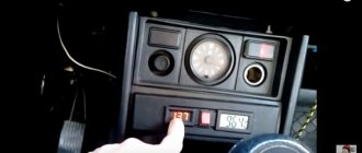
If the battery charging light comes on, the driver begins to worry. And the reason for this is serious - the battery capacity is unlikely to be enough to cover a significant mileage. And the reason that the lamp comes on may be a breakdown of the generator, battery, or a malfunction in the on-board network. All these factors should be considered more carefully so that in the event of an unforeseen situation, the breakdown can be quickly eliminated. To monitor whether the battery is charged, a special lamp is installed in the dashboard. It lights up if there is no charging.
How does a generator work?
Before you understand why the battery charging light comes on, you need to understand the principle of operation of the generator. Any car has two power sources. This is a generator and battery. They are connected in parallel. Therefore, when the engine is running, the generator supplies voltage to the battery and charges it. Moreover, there is one peculiarity. Regardless of the speed, the voltage at the generator output is always the same.
To stabilize it, a relay regulator is installed. Older cars used electromechanical-type designs. Modern ones use exclusively semiconductor ones. The lamp, which is installed in the dashboard, is included in the power circuit of the voltage regulator. It essentially serves as a fuse. To understand the essence, it is necessary to thoroughly study the principle of operation of the voltage regulator relay.
Generator device
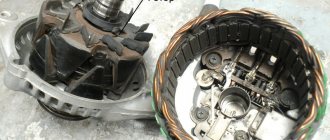
The design of a car generator implies the presence of its own rectifier and control circuit. The generating part of the generator, using a stationary winding (stator), generates three-phase alternating current, which is then rectified by a series of six large diodes and the direct current charges the battery. Alternating current is induced by the rotating magnetic field of the winding (around the field winding or rotor). Next, the current is supplied to the electronic circuit through the brushes and slip rings.
READ How to properly connect a mixing console to speakers
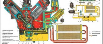
Generator structure: 1.Nut. 2. Washer. 3.Pulley 4.Front cover. 5. Distance ring. 6.Rotor. 7.Stator. 8.Back cover. 9.Casing. 10. Gasket. 11.Protective sleeve. 12. Rectifier unit with capacitor. 13.Latch holder with voltage regulator.
The generator is located at the front of the car engine and is started using the crankshaft. The connection diagram and operating principle of a car generator are the same for any car. There are, of course, some differences, but they are usually associated with the quality of the manufactured product, the power and the layout of the components in the motor. All modern cars are equipped with alternating current generator sets, which include not only the generator itself, but also a voltage regulator. The regulator equally distributes the current in the excitation winding, and it is due to this that the power of the generator set itself fluctuates at a time when the voltage at the power output terminals remains unchanged.
The principle of operation of a car generator
Connection diagram for the VAZ 2110-2115 generator
The alternator connection diagram includes the following components:
The principle of operation is quite simple: when the ignition is turned on plus through the lock, the ignition goes through the fuse box, light bulb, diode bridge and goes through a resistor to minus. When the light on the dashboard lights up, then the plus goes to the generator (to the excitation winding), then during the process of starting the engine, the pulley begins to rotate, the armature also rotates, due to electromagnetic induction, electromotive force is generated and alternating current appears.
Next, the diode passes plus into the rectifier block through a sine wave into the left arm, and minus into the right arm. Additional diodes on the light bulb cut off the negatives and only positives are obtained, then it goes to the dashboard assembly, and the diode that is there allows only the negative to pass through, as a result the light goes out and the positive then goes through the resistor and goes to the negative.
The principle of operation of a car DC generator can be explained as follows: a small direct current begins to flow through the excitation winding, which is regulated by the control unit and is maintained by it at a level of slightly more than 14 V. Most generators in a car are capable of generating at least 45 amperes. The generator operates at 3000 rpm and above - if you look at the ratio of the size of the fan belts for the pulleys, it will be two or three to one in relation to the engine frequency.
To avoid this, the plates and other parts of the generator rectifier are partially or completely covered with an insulating layer. The heat sinks are combined into a monolithic design of the rectifier unit mainly by mounting plates made of insulating material, reinforced with connecting bars.
Next, let's look at the connection diagram for a car generator using the example of a VAZ-2107 car.
Voltage regulator
Generators have two windings – rotor and stator. Moreover, the first one performs the functions of the excitation winding. We need to remember the theory: without a moving magnetic field, generating electricity is impossible. Therefore, it is enough to apply voltage to the rotor winding to obtain a magnetic field. Well, since the rotor is a moving part of an electric machine, it becomes clear that the magnetic field will rotate. And if the battery charging light periodically lights up, this indicates that there is a minor defect in the generator.
But why install a voltage regulator specifically in the power circuit of the excitation winding? After all, it is necessary to carry out stabilization in the stator circuit. This is true, but it’s worth remembering the theory: the output voltage depends on the magnitude of the magnetic field. Everything is very simple. It is enough to stabilize the power supply in the rotor winding circuit so that there are no oscillations at the output. It is much easier to stabilize small currents than large ones (can reach several tens of amperes).
Troubleshooting
Let's say that after starting the engine you notice that the battery charging light comes on. VAZ is susceptible to this problem, and it is relevant for any model. The following components need to be checked:
- Voltage regulator described above. On some vehicles it may be installed under the hood rather than inside the alternator.
- Diode bridge. One or more semiconductors may fail.
- Generator drive belt. It may be poorly tensioned, or it may have broken or slipped. If you hear a whistle, then you can judge that the bearing in the front cover is broken.
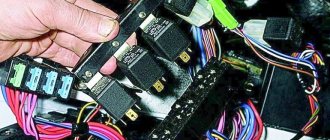
The cause may also be a broken wiring or poor-quality contact. First of all, check the wire going from the “+” of the generator to the voltage regulator. Very often it oxidizes and becomes covered with a layer of dust. Remove the brush holder and evaluate the wear of the brushes. If it is excessive, then it is necessary to replace it. Please note that on most cars the voltage regulator and brushes are combined into one unit. Another reason is a breakdown in the ignition switch. But this malfunction is accompanied by the fact that several lamps in the dashboard light up.
Tools for repairs
If the battery charging light comes on at rpm, most likely the belt is slipping due to low tension. But if everything is fine with this, you need to arm yourself with the following tools:
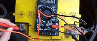
- Multimeter (preferably a dial voltmeter with a wide scale).
- A control light of 12 volts and 2-3 W power.
- Flat and Phillips screwdrivers.
- Pliers, sandpaper, knife.
With these tools on hand, you can begin repairs if the battery charging light comes on or there is another breakdown in the generator.
Breakdowns and their elimination
Let's say a voltmeter is installed in a car. And it shows that there is charging. The battery charging light also comes on periodically or does not light up at all. Measuring the voltage directly at the battery terminals shows exactly 12 volts. But the capacity is lost, the starter does not rotate, and the tape recorder has difficulty working. First of all, clean all the thick wires through which the battery is charged. Measure the voltage at terminal “30” of the generator. If it is larger than what is on the battery, strip the terminal or change the wire.
If the voltmeter on the dashboard shows the presence of charging, but the lamp does not light up, and the battery is discharged, despite the normal voltage in the on-board network, carry out a couple of simple steps. Turn on the maximum number of consumers and see how the voltmeter behaves. If the voltage drops sharply, tighten the alternator belt. It begins to slip because, under load, the rotor EMF counteracts the stator one. And it takes a lot of effort. In addition, one of the pulleys may simply wear out. Then even installing a new belt will not help.
Electronic warning lamp relays.
Also, in addition to electromagnetic relays, electronic relays. Of course, these relays are much more reliable. They were widely used in foreign cars produced in the 80s. The principle of these relays is to control the voltage of the on-board network. If the voltage is less than the nominal value, then the control lamp is turned on using an electromagnetic relay or a built-in transistor. On domestic cars, this principle is found on Nivas with a carburetor engine and an imported instrument panel, as well as on other models with imported instrument panels. As a control lamp, such panels used an LED, which was controlled by a unit built into the panel. Such cars were produced in a limited edition.
The most basic function of the generator is to charge the battery and power the electrical equipment of the engine.
A generator is a mechanism that converts mechanical energy into electrical energy. The generator has a shaft on which a pulley is mounted, through which it receives rotation from the engine crankshaft.
Interactive image of the generator circuit. Works on mouseover
A car generator is used to power electrical consumers, such as the ignition system, on-board computer, car lighting, diagnostic system, and it is also possible to charge a car battery. The power of a passenger car generator is approximately 1 kW. Car generators are quite reliable in operation because they ensure uninterrupted operation of many devices in the car, and therefore the requirements for them are appropriate.
Internal breakdowns
The above situation can occur when a semiconductor diode fails. If there is a break in the stator winding, a voltage drop under load is also observed. Disassemble the generator and diagnose the semiconductors. They have one-way conductivity. Ring the stator windings to identify a short to the housing. It is worth noting that a break can be found with a multimeter, but a bad contact is unlikely. For this purpose it is better to use a megohmmeter.
It is worth inspecting the generator brushes as well. If the battery charging light comes on at low speeds when the light is on, this also indicates the presence of the breakdowns described above. A lot depends on the brushes too. If they are 5mm or less in length, you can safely throw them away. And if the battery charging light comes on due to brush failure, the fault is very easy to find.
A few more common breakdowns
But most often it happens that the battery charging light does not light up, but there is a breakdown. Moreover, if the lamp itself burns out, the voltage on the excitation winding disappears. It is easy to identify a malfunction - you need to check the filament of the lighting fixture itself. But most often the lamp blinks and may light up briefly. Often the cause of this behavior is a broken contact in the power supply circuit of the field winding. To resolve, clean all connectors using a knife, sandpaper, or use a penetrating lubricant such as WD-40.
A little theory: scheme of work
To solve the existing problem, you must understand the essence of the interaction between the vehicle generator and the power source (battery).
While driving, the battery is in constant charging mode with a voltage of 13.6-14.2 Volts. As engine speed increases, the voltage at the generator output increases. But this is unacceptable.
To limit the voltage, a small relay regulator is inserted into the rotor excitation circuit. Its task is to reduce the current to a normal level (even with a significant increase in the speed).
The result is maintaining the battery charge voltage at a stable level. If the battery light is on, this indicates a lack of charging from the generator.
How does the scheme work? After turning on the ignition, voltage through fuse No. 10 (for VAZ-2107) is supplied to the battery charge indicator lamp.
Next, the “+12V” voltage passes through a diode, a built-in relay-regulator (we mentioned it above), a brush, a slip ring and a winding.
As soon as the rotor speed increases, the phase voltage also increases. As a result, the voltage at the terminals of the battery warning light is equalized and it goes out. At the same time, the battery is charging.
Generator connection diagram for VAZ 2107
The VAZ 2107 charging scheme depends on what type of generator is used. To recharge the battery on cars such as VAZ-2107, VAZ-2104, VAZ-2105, which have a carburetor engine, you will need a G-222 type generator or its equivalent with a maximum output current of 55A. In turn, VAZ-2107 cars with an injection engine use a generator 5142.3771 or its prototype, which is called a high-energy generator, with a maximum output current of 80-90A. It is also possible to install more powerful generators with an output current of up to 100A. Absolutely all types of alternating current generators have built-in rectifier units and voltage regulators; they are usually made in the same housing with brushes or are removable and mounted on the housing itself.
The VAZ 2107 charging circuit has minor differences depending on the year of manufacture of the car. The most important difference is the presence or absence of a charge indicator lamp, which is located on the instrument panel, as well as the method of connecting it and the presence or absence of a voltmeter. Such circuits are mainly used on carburetor cars, while on cars with injection engines the circuit does not change, it is identical to those cars that were manufactured previously.
Generator set designations:
Generator circuit VAZ-2107 type 37.3701
When the ignition is turned on, the plus from the lock goes to fuse No. 10, and then goes to the battery charge indicator lamp relay, then goes to the contact and to the coil output. The second terminal of the coil interacts with the central terminal of the starter, where all three windings are connected. If the relay contacts close, then the control lamp lights up. When the engine starts, the generator generates current and an alternating voltage of 7V appears on the windings. Current passes through the relay coil and the armature begins to attract, and the contacts open. Generator No. 15 passes current through fuse No. 9. Similarly, the excitation winding receives power through the brush voltage generator.
READ How to connect a Ford Focus 2 radio to your phone
Reasons why the battery charging light is on
In fact, there are many reasons why the battery light comes on and does not go out. These include:
- Loosening of the belt tension on the generator, its wear or damage;
- fuse blown or deterioration of contact quality in the connectors of the mounting block;
- breakdown of the relay regulator, diode bridge, additional diodes;
- the appearance of a break in the generator excitation circuit;
- decreased quality of contact at the battery terminals or generator output;
- generator brush wear;
- lack of high-quality contact of the ground wire.
What to do if the battery charging light is on?
First of all, get out of the car and, with the engine running, measure the voltage at the battery terminals (do not remove the clamps under any circumstances).
If charging is in progress, the voltage should be at 13.6-14.2 Volts. In the absence of charge, the voltage level will be much lower - about 12 Volts.
To fix the problem, prepare the following tools:
- twelve volt indicator light,
- two screwdrivers (flat and Phillips),
- multimeter,
- pliers,
- knife,
- Use sandpaper to clean contacts.
So let's get started:
1. The readings of the on-board voltmeter indicate the presence of a charge, the charge signal lamp on the dashboard does not light up, there are about 12 Volts at the battery terminals, and the battery itself is almost discharged.
In such a situation, clean the wire connections on the power source itself. If these measures are useless, measure the voltage level at terminal “30” of the generator itself.
Place one multimeter probe on this terminal, and the other on ground. If the voltage here is much higher than at the battery, then strip the thirtieth terminal. If necessary, replace the wire from the generator to the battery.
2. The voltmeter on the dashboard and the lamp show the presence of a charge, but the battery is discharged.
The voltage on the battery is normal (about 14 Volts). Turning on a load (for example, headlights) causes the charge arrow to shift to the extreme left position.
The main reason is weak belt tension on the generator pulley (tension the belt, and if it is damaged, replace it).
This problem can also be caused by a breakdown of one of the diodes, as well as a break in the stator phase winding. Turn off the ignition and check the diodes with a multimeter. In case of breakdown, replace them.
Check the generator brushes. To do this, take them out and measure the length. If it is less than five millimeters, then it is better to replace the brushes.
3. When you turn the key in the ignition, the charge warning lamp does not light up, the charge sensor does not work, and there is no charge on the battery. The reason is a blown fuse.
Its designation is F10, rating is 10 Amperes. If installing a new fuse does not produce results, then the reason must be sought in the ignition relay or the lock itself.
4. After turning on the ignition, there is no charge, all devices work, the control warning lamp does not light up.
The check is simple - remove the wiring from terminal “sixty-one” of the generator and connect it directly to the “minus” (car body). If the light comes on, then the cause of the problem is the generator field winding.
The second option is bad contact in the connector. If after cleaning there is no result, then there is a risk of the lamp itself burning out.
5. When you turn the key in the ignition switch, the charge lamp lights up, and after starting it continues to light up. In this case, there is no charging or appears periodically. The reason is insufficient contact of the wire at the connector with the dashboard (it may oxidize).
Finally, check the relay regulator. To do this, apply voltage from the battery to its contacts. If there is 12 volts on the brushes, then the relay is working properly. If not, the device must be replaced.
If you have problems charging the battery (the warning light does not go out or does not light up at all), then check all versions.
But, as a rule, the problem is always on the surface, and the cause is poor contact, a burnt out light bulb or a faulty relay regulator. Good luck on the roads and of course no breakdowns.
GENERATOR VAZ 2101 BATTERY CHARGING LAMP AND PRINCIPLE OF OPERATION
The principle of potential difference or the meeting of constant and alternating voltage in the winding of an electromagnet.
Brown-white in the first case for the generator and in the 2nd for the RS-702 relay . But let's take a closer look. In the diagram for switching on the new generator, the control lamp from the combined instrument goes with an orange wire back to the fuse block, as is the case with both diagrams for 2107. But in the second diagram it also comes white-brown, but it’s not brown that goes out from the lamp, but white-black the wire and it is very important that it goes to the ground. This is the whole nuance and error in the diagram for 2107 and the G-222 generator . I think the whole problem is that the one who drew the drawings for the site in electrical engineering saw two identical drawings at first glance, found the differences as it seemed to him only in the presence of the RS-702 relay , and everything else was a banal Copy-Paste, which then led to a headache pain.
When you realize this, the error becomes visible to the naked eye. If you look again at the incorrect diagram given on the site, you can see that when the RS-702 relay , we get a ring (shown by the red line) and the light bulb in the circuit simply cannot light up since there is no circuit through it; it has the same 12 on both sides ignition on . You need to tear off the second wire from the lamp that goes to 12 when igniting and put it on the ground, which is what I did. The wire on the dashboard does not go very well, after it the orange one is still fed to the indicator of insufficient brake fluid level and I had to cut the tracks.
A small lyrical digression. Knowing now where I have 12 from the ignition on, I removed the snot from the instrument lighting that went to the yellow-blue wire of the button from the heater stove. I covered the places of my intervention with tsaponlak to keep sin and oxidation away. The light is on as it should be, then we start the engine and it goes out for natural reasons.