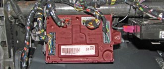
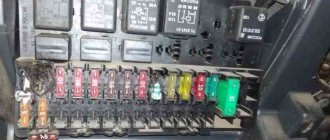
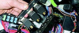
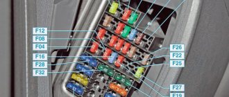
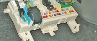
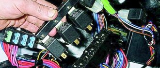
Regardless of the generation of UAZ Patriot, the standard location of the fuse box is in the passenger compartment, to the left of the steering column.
The number of modules in older models (before 2014) was smaller: 8 relays, 12 fuses. In the 2015 versions of the UAZ Patriot, the number was increased to 11 and 30 pieces, respectively.
Where is the additional unit located: installed under the hood, in the engine compartment, behind the battery.
Due to various reasons, including a short circuit, natural wear and tear, the melting elements burn out and fail. Current does not flow to mechanisms and units.
Replacing modules with new ones is not a difficult process, but requires care on the part of the repairman. Violation of installation technology can lead to repeated failure.
Fuses and relays in the cabin
The fuse and relay box is located inside the car under a cover on the instrument panel to the left of the steering column.
2005-2011
Circuit breakers
F1 (5A)
- Lighting of switches and controls
- Left side marker lights
F2 (7.5A)
- Low beam right headlight
F3 (10A)
- High beam right headlight
F4 (10A)
- Right fog lamp
F5 (30A)
- Power window system
- Electric sunroof
F6 (15A)
- Portable lamp socket
F7 (20A)
- Sound signals
- Electric mirrors
F8 (20A)
- Heated rear window
- Heated exterior mirrors
- Light control module (LCM)
F9 (20A)
- Glass cleaners and washers
- Additional interior heater
F10 (20A)
- Cigarette lighter
F11 (5A)
- Side lights on the starboard side
- License plate light
F12 (7.5A)
- Low beam left headlight
F13 (10A)
- Left high beam
- Headlight high beam indicator
F14 (10A)
- Left fog lamp
F15 (20A)
- Electric door lock system
F16 (10A)
- Alarm
- Direction indicators
F17 (7.5A)
- Lighting lamps
- Brake light switch
F18 (25A)
- Heater
- Switch for heated rear window and exterior mirrors
F19 (10A)
- Instrument cluster
- Reversing light switch
F20 (7.5A)
- Rear fog lights
F21 (10A)
- Spare fuse
F22 (20A)
- Spare fuse
F23 (30A)
- Spare fuse
Relay
K1
- Absent
K2
- Windshield wiper relay
K3
- Turn signal interrupter relay
K4
- Low beam relay
K5
- High beam relay
K6
- Additional (unloading) relay
K7
- Heated rear window relay
K8
- Fog light relay
2012-2014
Circuit breakers
F1 (5A)
- Side light left
F2 (5A)
- Side light right
F3 (7.5A)
- Low beam headlights right
F4 (7.5A)
- Low beam left
F5 (10A)
- High beam headlights right
F6 (10A)
- Left high beam headlights
F7 (7.5A)
- Fog light
F8 (20A)
- Door lock
F9 (10A)
- Alarm
F10 (10A)
- Cl. 5 XP1 KP
- Reversing lamp switch
- class 1 speed sensor
- class 4 central lamps
- class 2 hazard switches
F11 (30A)
- Window lifters
F12 (20A)
- Cigarette lighter
- Seat heating
F13 (20A)
- Sound signal
F14 (20A)
- Heated tailgate glass
- Heated exterior mirrors
- Light control module (LCM)
F15 (20A)
- Cont. 11 X2
- Wiper switch
- Wiper
- Rear heater switch
F16 (10A)
- Right fog lamp
F17 (10A)
- Left fog lamp
F18 (25A)
- Heater
F19 (7.5A)
- Brake light switch
- Lighting lamps
F20 (5A)
- Mirror control
F21 (10A)
- Air conditioning compressor
F22 (15A)
- Plug sockets
Relay
K1
- Fog lights
K2
- Fog lights
K3
- High beam
K4
- Low beam
K5
- Unloading relay
K6
- For engines ZMZ 40904, 40905: Additional heater
K7
- Compressor
K8
- Direction indicators
- Alarm
K9
- Windshield wiper interrupter with pause adjustment
2014-2019
Circuit breakers
F1 (10A)
- RK "Dymos" class 15
F2 (15A)
- Interior socket
F3 (10A)
- Air conditioning compressor
F4
- 2014-2015 (5A): Mirror control
- Electrical package control unit, terminal 30
F5 (7.5A)
- Brake light switch
- Interior lamps
- Glove box light
- Luggage compartment lamp
F6
- 2014-2015 (25A): Heater
- Heating and air conditioning system
F7 (10A)
- Left fog lamp
F8 (10A)
- Right fog lamp
F9 (20A)
- Wiper switch
- Wiper
- Driver switch block
- Rear passenger switch block
- Rear body heater
- Auxiliary heater switch
F10 (20A)
- Heated tailgate glass
- Heated mirrors
- Light control module (LCM)
F11 (20A)
- For ZMZ-51432 engines: Sound signal
F12 (20A)
- 2014-2015: Cigarette lighter
- Seat heating
- Cigarette lighter
F13 (30A)
- RK "Dymos" class 30
F14
- 2014-2015 (30A): Window lifters
- Window regulators (driver's door module)
F15
- 2014-2015 (10A): Cl. 5 XP1 KP
- off reverse lights
- class 1 speed sensor
- class 4 central lamps
- class 2 hazard switches
- Cl. 34 instrument cluster
F16
- 2014-2015 (10A): Hazard warning
- Airbag
F17
- 2014-2015 (20A): Door lock
- Media system (radio with audio player)
F18
- 2014-2015 (7.5A): Fog light
- Differential lock
F19 (10A)
- Left high beam headlights
F20 (10A)
- High beam headlights right
F21 (7.5A)
- Low beam left
F22 (7.5A)
- Low beam headlights right
F23 (5A)
- Side light right
F24 (5A)
- Side light left
F25 (60A)
- Heated windshield
F26 (10A)
- Reserve
F27 (10A)
- Reserve
F28 (30A)
- Reserve
F29 (25A)
- Reserve
F30 (20A)
- Reserve
Relay
K1
- Fog light relay
K2
- 2014-2015: Relay for turning on the heated glass of the tailgate and mirrors
K3
- High beam relay
K4
- For ZMZ-40905 engines: Relay for additional electric heater pump
- Low beam relay
K5
- 2014-2015: Low beam relay
- Auxiliary interior heater relay
K6
- A/C compressor relay
K7
- 2014-2015: Turn signal and hazard warning light switch
- Relay for turning on the heated glass of the tailgate and mirrors
K8
- Windshield wiper interrupter with programmable pause
K9
- Additional (unloading) relay
K10
- Heated windshield relay (unloader)
- Fuel tank switching relay (for vehicles with UAZ switchgear)
K11
- Heated windshield timing relay
K12
- 2016-2019: Rear axle differential lock relay
Blocks under the hood
Fuse and relay box
It is located under the hood on the left side, next to the battery and is closed with a protective cover.
Scheme
Explanation of fuses
| F1 | Sound signal |
| F2 | Not installed |
| F3 | Electric fan 2 |
| F4 | ABS (ESP) |
| F5 | Devices |
| F6 | Gasoline pump |
| F7 | Starter |
| F8 | Electric fan |
| F9 | Integrated microprocessor engine control system (CMPSUD) |
| F10 | ABS (ESP) |
| F11 | Pre-start heater |
| F12 | Pre-start heater |
| F13 | Pre-start heater |
| F14 | Not installed |
| F15 | Not installed |
| F16 | Not installed |
| F17 | 60/90A Mounting block, Heated windshield |
| F18 | ABS (ESP) |
| F19 | Mounting block |
Relay
| R1 | Starter relay, electric fan relay 1 |
| R2 | Heater relay, Tailgate washer window time relay (old style unit) |
| R3 | Heater relay, Horn relay (old style unit) |
| R4 | Horn relay, CMPS UD relay (old-style unit) |
| R5 | Relay CMPS UD, Electric fan relay (old style unit) |
| R6 | Electric fan relay, Electric fuel pump relay (old style unit) |
| R7 | Electric fuel pump relay, Electric fan relay (old style unit) |
| R8 | Electric fan relay, air conditioning relay (old style unit) |
| R9 | Compressor relay (old style unit), engine control relay |
| R10 | Recirculation flap control unit relay (old style unit), starter relay 2 |
Additional blocks
Battery block
On the positive terminal of the battery on cars with automatic transmission, there may be an additional fuse block consisting of 2 high-power 100A fuse links protecting the fuse blocks.
Air conditioning relay and fuse box
It is located on the right under the hood of the car.
Scheme
Glow plug relay and power fuse
The glow plug relay and the glow plug power fuse for vehicles with an Iveco engine are located under the hood on the left side on the front panel.
general description
| F1 | 7.5A A/C compressor clutch |
| F2 | 30A Fan 1 |
| F3 | 30A Fan 2 |
| F4 | 60A Glow Plug Power Fuse |
| Relay | |
| K1 | Interior heater fan relay |
| K2 | Recirculation flap relay 1 |
| K3 | Recirculation flap relay 2 |
| K4 | Compressor clutch relay |
| K5 | Fan relay 1 |
| K6 | Fan relay 2 |
| K7 | Glow plug relay |
What are they needed for
As in any other vehicle, the UAZ Patriot fuse box is designed to extend the life of the vehicle's electrical system . All main electrical circuits are protected by low melting point fuses. This allows:
- divide the circuits into two groups (control and power);
- prevent overloading of electrical wiring.
As a result, the correct operation of UAZ Patriot fuses will allow you to avoid serious problems with electrical equipment in the event of surges in the system. If the voltage increases, the fuse will blow, so you will not have access to just one specific option. Otherwise, the entire electrical system would be at risk.
Video review of UAZ Patriot fuses:
Fuse layout diagrams for UAZ Patriot
Inside every car, including UAZ cars, there is an extensive electrical system. It performs many important functions, so it must work reliably in any conditions, including emergency situations. The elements of the electrical circuit are protected by UAZ Patriot fuses.
Description of fuses on UAZ Patriot
Fuses in all modifications of the UAZ model range, including pickups, are standard and are manufactured by various companies, both domestic and foreign.
They contain a fuse-link and are disposable circuit breakers. After activation they must be replaced. The main selection criteria are the rated current and voltage.
In older UAZ models, cylindrical products were used.
Practice has shown the inconvenience of using such parts, and therefore they were replaced with flag elements, sometimes called knife elements.
If the car still has cylindrical fuses, then they can be replaced entirely, i.e. block, with modern details. The breakers are assembled into modules, where, in addition to them, relays are installed.
One of the modules is located in the cabin, the other two are in the engine compartment.
The cabin unit has several modifications, depending on the year of manufacture:
- in UAZs until 2007, the safety block from the VAZ 2110 sedan was used;
- then the plant’s specialists developed their own module, which was installed in cars from 2007 to 2011;
- it was replaced by a completely redesigned block with a different arrangement of parts.
The motor module is simpler, but no less important. There are mounting blocks of old and new models. The electrical elements inside them are placed differently. The third module, depending on the engine type, regulates the operation of the air conditioner or diesel glow plugs.
Fuse location
In all UAZ models, cabin fuses are located in the front, to the left of the steering wheel, in the lower part of the dashboard under the cover. The second module is located under the hood behind the battery. The third engine compartment module is located on the right wing and is closed with a lid.
Schemes by location
If you divide the plane of the block from the VAZ 2110 into 4 rows, then in the first upper row there are 2 relays K4 and K6 and 3 fuses F1-F3 between them. The second row is occupied by elements K1, K2, K3, K5 and K7, the third and fourth rows are filled with circuit breakers F4-F23, 10 pcs each. each has a total of 23 elements.
A self-developed module is described by six rows:
- the first two lines are occupied by fuses F1 to F24, 12 pcs each. in a row;
- the next two contain 3 relays K1-K6;
- then there is a row where K7-K10 and F26-F30 are located;
- the final 6th row is reduced: it contains only parts F25 and K11.
The unit, designed for installation in a car after 2011, is structured as follows:
- all fuses are collected in the top two lines, 11 pcs each. in each;
- then there are 2 rows of relay elements, from K1 to K7, where K5 is located in the inter-row space;
- The scheme is completed by a row with parts K8 and K9.
average cost
Electrical fuses are sold both individually and in sets. The cost of an individual element ranges from 14 to 20 rubles. Blister sets contain 10-12 pcs. and cost from 150 to 200 rubles. As a bonus, some blisters have plastic pliers for removing parts.
What are fuses needed for and what are they responsible for?
Fusible switches are needed to protect the electrical circuit, since in the event of a short circuit or an increase in current above the permissible value, the fusible link inside them burns out first, and not the wires and parts.
Switches located inside the passenger compartment control the electrical circuits of the following mechanisms and systems of the vehicle:
- Headlights, side and signal lights, including control circuits for each turn signal.
- Electric windows, lockers for each lock, radio.
- Cleaning (windshield wipers), flushing and heating windows.
- Supply of audio signals and drive mirrors.
- Cigarette lighter, seat heater and interior heater.
- Interior lighting, incl. central lampshade.
- Plug sockets.
The module located under the hood is responsible for the following devices and systems:
- Klaxon and fans.
- Gasoline pump.
- Tracking the speed of rotation of the wheels, i.e. for the system, also called anti-lock braking.
- Anti-slip and brake force regulation.
- Starter (including starter relay).
- KMPSUD (integrated microprocessor engine control system).
- Instruments on the front panel.
Replacement features
To replace burned-out disposable circuit breakers, parts with the same current and voltage ratings should be prepared. As a temporary solution, it is possible to install an element of a higher rating in order to replace it with the required one in the near future. It is strictly not recommended to replace the fuse with a coin or twisted wire.
Tools include a set of flathead screwdrivers, a power block wrench, tweezers, plastic pliers or a spatula. In poor lighting conditions, a portable rechargeable head-mounted flashlight is recommended.
To check the integrity of the fuses in the interior module, you need to open the cover by turning the fixing screw and pull it out. On the inside of the cover there is explanatory information, including markings and pinouts.
First you should look for the burnt part visually. There may be traces of burning on it. If the housings are made of high-quality plastic, then there will be no traces of combustion and the elements must be removed one by one with tweezers or tongs.
The car accessories market offers products integrated with a high-impedance light bulb or LED, which light up and glow after the fusible link burns out, which makes it much easier to find the faulty part. The parts in the engine compartment module are checked and changed in the same way.
In some cases, 60 and 80 A fuses are installed separately in the power module, located in the engine compartment and closed with a snap-on plastic cover.
They are attached to the terminal pads with nuts or bolts, which ensures a reliable connection without chatter and melting of housings and contacts.
When replacing, the cover snaps off, the bolts or nuts are unscrewed, the burnt jumper is removed, and a new one is installed in its place. The fasteners are screwed in, the lid is put in place and snapped into place.
Helpful care tips
Some basic tips:
- Parts are purchased in advance individually or in sets, always from original brands and in trusted stores.
- The insulation of wires and cables, as well as contact connections in mounting blocks, are periodically inspected. If the integrity of the insulation is compromised and the contacts are loose, the wiring and contact blocks should be replaced.
- The module covers under the hood are periodically opened to check for moisture and dried to prevent short circuits.
It is advisable to trust the performance of operations 2 and 3 to professionals in specialized auto repair shops during scheduled technical inspections, when changing the oil or repairing other components of the car.
