Modern AVTOVAZ SUVs use injection power units. If a malfunction is detected in the electrical equipment of the car, you should first check the serviceability of the fuses and relays. Next, we will show where the mounting block is located (fuse box or black box), as well as the location of the elements inside it.
Fuses and relays Niva 2121
The cars Niva 2121, Niva 21213, Niva 21214 carburetor, injector were considered.
another name for VAZ 2121, VAZ 21213, VAZ 21214, Niva 4x4.
Location of fuses and relays Niva.
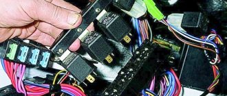
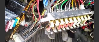
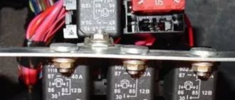
The main fuse box is located in the passenger compartment under the instrument panel, to the left of the steering wheel.
1 — engine control system fuse block; 2 — windshield wiper relay; 3 — fuse blocks; 4 - engine control system relay block
Main and additional fuse box Niva.
To access the blocks, pull the latch located on top of the blocks and remove the cover.
Fuse designation (rated current, A)
Heater Blower Motor Switch, Tailgate Defroster Switch, Tailgate Wiper Motor, Tailgate Wiper/Washer Switch (Windshield Washer Pump)
Steering column switch, windshield wiper motor, hazard warning switch, breaker relay (in turn signal mode), reverse light switch, instrument cluster (coolant temperature gauge, fuel level gauge, tachometer, indicator lamps: turn indicators, differential locks, parking brake, emergency condition of the service brake system, insufficient oil pressure, fuel reserve, battery charge)
Left headlight (high beam), high beam indicator lamp
Right headlight (high beam)
Left headlight (low beam)
Right headlight (low beam)
Side light lamps in the left front and left rear lights, license plate lights, side light indicator lamp
Side light lamps in the right front and right rear lamps, backlight lamps for the instrument cluster, cigarette lighter, switches, heating and ventilation control unit
Hazard switch, breaker relay (in hazard mode), heated tailgate glass relay contacts
Sound signal, interior lamps, brake lamps in the rear lights
Fog light relay contacts in rear lights
Source
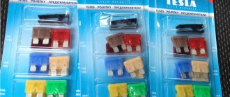
Reasons for failure
As a rule, frequent relay breakdowns are explained by the low quality of components, both supplied from the factory and those still alive “cooperatives”. You can only combat this by choosing carefully or having a handful of other replacement parts. Repair is impractical due to the cheap cost, although there are examples of restoration “for fun.” The only difficulty is access to the place where the Niva turn signal relay is located; changing it is a matter of 2 minutes.
Another reason that can kill the breaker is increased voltage in the on-board network as a result of failure of the generator components and the voltage relay regulator. A short circuit is also possible. In any case, the circuit is examined, starting with a simple one - the state of the fuses.
The symptoms of the malfunction have characteristic features and are distinguishable from a burnt-out incandescent lamp or circuit damage. So, if the problem is in the relay, then the driver will see one of the following manifestations when turning on the turn switch:
- The indicator lamp does not light up, the turn signals are extinguished;
- The indicator on the dashboard and the turn signals are constantly on;
- There is an uncharacteristic crackling sound (clicking) when the relay operates;
- There is a change in the pace of functioning within a short time;
- Different response frequency compared to alarm.
Where are the blocks and relays located in Niva 21214 and 21213
The main power supply in these models is located under the lower edge of the instrument panel protection. Additional fuses in Niva 21214 for the injector are located to the left. This block is responsible for controlling fuel injection. There are also relays for monitoring the operation of the wipers and a set responsible for the motion control system.
Another fuse box is installed in the body to the left of the main one. They are responsible for the cooling system and how the engine works. There is also a diagnostic connector. The relay that controls the starter is located either next to the main power supply, or under the hood next to the brake fluid reservoir.
symptoms
How to replace the stove tap on Niva 21214
The symptomatology of the malfunction has its own characteristics and differs from the burning of an incandescent lamp or damage to the circuit. Thus, if the problem is in the relay, then when turning the switch the driver will see one of the following manifestations:
- The indicator does not light up, the turn signals are off;
- The dashboard indicator and turn signals are constantly on;
- When the relay operates, an uncharacteristic crack (clicks) occurs;
- Within a short time there is a change in the pace of functioning;
- Different response rate compared to alarm.
https://youtube.com/watch?v=SqqIBAU8osQ
Engine control system fuse box
Scheme
Designation
| 1 | 15A 1* ECM sensors Starter relay Canister purge valve |
| 1 | 7.5A 2* Controller |
| 1 | 3: Electric fuel pump relay (contacts) Electric fuel pump |
| 1 | 30A 4.5* Cooling fan |
| 2 | 15A 1* Injectors Ignition coils ECM controller Right electric fan relay Left electric fan relay |
| 2 | 15A 2* Electric fuel pump relay (contacts) Electric fuel pump |
| 2 | 30A 3* Reserve |
| 2 | 30A 4.5* Cooling fan |
| 3,4 | 30A 1* Electric fans (right, left) Right electric fan relay Left electric fan relay |
| 3 | 15A 2* Main relay |
| 3 | 15A 3* Controller |
| 3 | 15A 4* Ignition coil, power supply for fan relay control, controller, injectors |
| 3 | 15A 5* Ignition relay |
| 4 | 15A 3* Main relay Electric fan relay (winding) Electric fuel pump relay (winding) Vehicle speed sensor Canister solenoid valve Oxygen sensor Mass air flow sensor Controller |
| 4,5 | 30A 2* Electric fan relay (winding) (right, left) Electric fan motor (right, left) |
| 4 | 15A 4* Mass air flow sensor, phase sensor, heating oxygen sensor (two), canister purge valve, DS |
| 4 | 15A 5* Electric fuel pump |
| 5 | 15A 1* Electric fuel pump Electric fuel pump relay |
1* - 2014-2016, 2* - 2010-2012, 3* - 2007-2008, 4* - Cars with Bosch ME17.9.7/M74 controllers, 5* - Cars with 7.9.7+ controllers.
Diagram for switching on the dimensions of the Niva 21213 car |
Scheme for switching on the external lighting (dimensions) of the Niva 21213 car
Elements of the diagram for switching on the dimensions of the Niva 21213 car
1. Side lamps in the front lights of the car. 2.Fuse block. 3.Outdoor lighting switch. 4. Instrument lighting switch. 5. Indicator lamp for turning on the dimensions in the instrument cluster. 6.License plate lights. 7. Side light lamps in the rear lights.
A - to the lighting lamps of the instrument cluster, switches and backlight display.
Notes and additions
More diagrams of the Niva 21213 car
— Connection diagram for low and high beam headlights Niva 21213
— Wires for the rear lights of the Niva 21213 car, diagram
— Connection diagram for generator 9412.3701 for Niva 21214
— Body clearances of the Niva 21213 car, diagram
— Connection diagram for direction indicators Niva 21213
Replacing fuse Lada 2131 (VAZ 2131)
Every car has a fuse box that is responsible for the operation of certain components of the vehicle. If certain fuses fail, the operation of some elements becomes impossible, but if the unit itself breaks down, the vehicle simply will not be able to continue moving. Today we will tell you what role the VAZ 21214 Niva injector fuses play, what the diagram looks like, where the block is located and how to replace it.
The fuse block (hereinafter referred to as the fuse block), unlike traditional models of the domestic automobile industry, is located in the vehicle interior. In particular, it is located on the driver's side under the steering wheel.
If any electrical circuit element in a car stops working (lamps, interior lights, heater, power windows), then car owners first check the power supply elements.
As a rule, the problem is resolved by replacing the fuse.
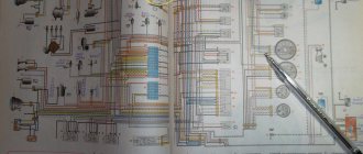
What does the power supply circuit itself look like? This question may be of interest to Niva owners. Below we will look at the electrical circuit of the unit with a description of all the components responsible for the operation of certain devices in the car.
In accordance with the diagram, we will consider the meaning of the BP elements. This electrical circuit is universal for all Niva cars.
It should also be noted that in VAZ 21214 injector cars there is another power supply unit with injection system components. It is located separately from the main power supply on the left side under the steering wheel.
In the case of the first described power supply unit, if the elements of the device begin to fail, this will in no way threaten the performance of the car, of course, with the exception of breakdowns of some components. However, in the case of the second power supply, if at least one component shorts out and does not work, the VAZ 21214 injector engine will not start.
Replacing the power supply with your own hands
Below we will look at the process of replacing the power supply with your own hands. To replace, you will need a new power supply and a socket head set to “8”.
Replacing the alternator belt
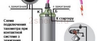
233747 turn relay connection diagram
To change the Chevrolet Niva alternator belt, you need to use the following tools:
In a Chevrolet Niva car, replacing the alternator belt is as follows:
- You need to remove the connector from the crankshaft position sensor.
- Unscrew and remove the bolt that secures the sensor.
- The nut securing the generator needs to be loosened slightly and moved towards the block. If the generator is displaced, its belt will loosen and can be removed without problems.
- Using a jack installed on the side where the generator is located, raise the car by engaging first gear.
- Pull the belt until it moves away from the pump pulley. Rotate the wheel so that the place of the guy moves onto the pulley.
- Then remove the belt from the other pulleys.
- The new one must first be put on the generator pulley and the crankshaft pulley, and only then put on the pump pulley.
- Turn the wheel until the belt is on the pulley.
- Put the generator in place, and tighten the belt, attach it to the bracket with a nut.
- Replace the crankshaft position sensor.
The process of replacing the alternator belt is complete.
Additional relay block
This block is located above the gas pedal.
Scheme
Description
A little higher, above the block, a relay can be installed - a breaker for the turn signals and hazard warning lights.
Separate fuses and relays can be installed under the hood: on cars with ABS, on the left side of the engine compartment near the ABS hydraulic unit, a block with fuses is additionally installed that protect the elements of the anti-lock brake system and the starter relay not far from the starter itself.
Recommendations
I replaced the ignition switch contact group, now everything works as before!Thanks for the advice!
And also interesting: Do-it-yourself modifications to the Niva 2121 “
The dimensions from the factory work without ignition. I often forget to turn it off, I lock the car, and the lights are on and the lights are on. Of course there is no stove.
And in principle, you shouldn’t turn on the heater fan until you start the engine!
And my dash doesn't light up and the heater fan doesn't work when the ignition is off. How it should be!
The tidy should light up when the lights are turned on.
It doesn't light up for me. Only when the ignition is turned on.FLASH-X3!
Either there is a problem in the lock, or in the button for turning on the dimensions (headlights), there is simply nothing to break.
Turn signals and hazard lights do not work
After being parked for 4 days, I came to pick up the car, it started and drove as usual, but it turned out that the turn signals and emergency lights were not working - the lights were not on, the arrows on the panel were not blinking. Everything else is completely normal. Checked the fuses - OK. The light bulbs are all OK, and they couldn’t burn out all 8 at once. I listened in silence - when turning on the turn - to quiet frequent clicks from the turn signal + hazard warning light relay.
I pulled out this relay, checked it at home without a load, without light bulbs - I applied 12 V where needed - the emergency lights click as expected, the turn signals - often, twice as often as usual, because... without load. From this I conclude that the relay is also in order.
I rang the connector block as written in the Prius wiring diagram - everything is also like in the book, it rings as it should.
But when I put everything together, it doesn’t work! Again light frequent clicks of the relay and then silence.
What could it be, what did the dog rummage through, give me some ideas. And now I can’t even come to the service center.
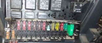
Mounting blocks for Lada 4×4 2021
The main and additional units are located in the cabin to the left of the steering wheel, under the instrument panel. The blocks contain fuses of the “Cylinder” size, ten and six fuses, respectively. The ratings and purpose of the fuses are indicated in Table 4 “Circuits protected by fuses”:
Fuse block of standard size “Standard”. The block is located on the left side under the upholstery and contains fuses that are designed to protect engine control system devices. The ratings and purpose of the fuses are shown in Table 5:
The fuse and relay box is located on the left side of the steering column under the instrument panel. The block contains two “Standard” size fuses, which are designed to protect the circuits of the electric fuel pump, electric windows and electric mirrors. The ratings and purpose of the fuses are shown in Table 6:
The fuse and relay box is located on the right side of the steering column under the instrument panel. The block contains one “Maxi” size fuse and two “Standard” size fuses, which are designed to protect the circuits of the hydraulic unit of the anti-lock braking system. The ratings and purpose of the fuses are shown in Table 7:
Replacement method
For operations you need:
- Key head to “10” (preferably with a ratchet mechanism);
- Plastic puller or similar device;
- Pliers;
- Phillips screwdriver.
1. Take a screwdriver and loosen the instrument panel valve from the two self-tapping screws.
2. Carefully apply the shield to yourself, overcoming the resistance of the pair of latches at the top of the part.
3. Unscrew the dashboard using the “10” key.
4. Slowly dismantle the instrument cluster, while at the same time getting rid of the union nut of the flexible speedometer drive shaft using pliers.
5. Disconnect the wires by removing the two gaskets.
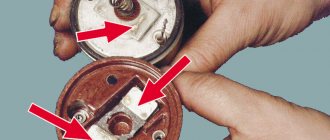
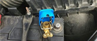
After establishing the place where the relay turns to the Niva, unscrew the nut to “10”, by the way, disconnect the 3 wires from the “ground” from the stud. Pull the device towards you and then, using a slight swing, pull the shoe out. Replace the switch with a new one as shown in the photo.
The assembly process is performed in reverse order. The criterion for performance is the rhythmic flashing of signals after activation of the gear lever or alarm button. A small deviation in operating speed from the 2121 conveyor is considered acceptable.
Chevrolet Niva
: fuses and relay box
Each car has electrical circuits in its design that power certain electrical devices. Chevrolet Niva is no exception and is also packed with electronics. From time to time, electrical devices malfunction and require troubleshooting. The first elements to be inspected and repaired are fuses. In addition to the fuses, it is also worth inspecting the serviceability of the relay. Thus, today’s article is devoted to such important elements of the Chevrolet Niva electrical circuit as the fuse and relay box.
If there is a malfunction of one or another device in the car, then first of all it is worth looking for the cause of the breakdown in the protective fuse block. These elements are designed to protect important devices from various factors: short circuits, increased current. Let's look at what protective mechanisms are available in Shevik and what they are responsible for, but first we should figure out where to find this fuse and relay box.