Internal structure and principle of operation
The heating system installed on the VAZ-2109 has its own differences and features compared to other cars in the AvtoVAZ line.
The heater consists of a pair of plastic casings (on the right and on the left), which are connected to each other along the entire perimeter with clamping brackets. A special flagellum is placed in the grooves of the casings to seal it well. The fan supplies air flow to the interior of the machine. The VAZ-2109 stove is designed so that the fan can be easily removed independently from the engine compartment.
An electric motor of type 45.37230 is attached to the casing, and a fan is located on its shaft. To obtain its desired rotation speed, additional resistance was provided. It was attached to the left side of the hole in the heater casing using a screw.
Heating system radiator
A radiator is built into the stove body to heat the air flows, which then blow into the cabin. Using three screws, this element of the system is screwed to the right casing and sealed with a polyurethane foam gasket.
The radiator design is a combination of:
- 2 rows of tubes.
- 2 rows of cooling plates.
- 2 plastic tanks.
It has two pairs of pipes, it is connected to the cooling system by rubber pipes, where coolant circulation is ensured using a pump. In the valve casing, on the axis of the supply line, there is a plate valve, which has a hole; it allows the coolant to pass through. The valve lever is connected by a rod to the handle lever, which also controls the process of heating the air flow. If you turn this lever, the hole in the valve will open the line for coolant to enter the radiator.
To ensure uniform heating of the car interior, the stove has two central nozzles, as well as left and right, to which air ducts are connected.
Exhaust ventilation
The car is equipped with exhaust ventilation, which circulates air from the interior to the street. It is located behind the body openings for the side windows.
Air also passes out through the deflectors when the car moves. The ventilation process is carried out due to the vacuum that occurs at the deflectors during movement. Air is sucked out from the rear of the cabin under the deflector trim; for this purpose, the rubber valves are pressed out and the air flow goes out through the deflector hole to the street.
Rubber valves are needed to prevent outside air from entering the car interior.
Equipment diagram for VAZ-2109 injector
The VAZ 2109 wiring for the injector has many connectors for connecting sensors to the computer.
- TPS (throttle position sensor);
- DPKV (crankshaft position sensor);
- DT (temperature sensor);
- DSA (vehicle speed sensor);
- Canister purge valve;
- MAF (mass air flow sensor);
- DD (knock sensor) and others.
The weak point of the harnesses is the power wiring on the bottom shelf of the radiator, which is constantly exposed to high temperatures and in this place it is in no way protected from water and dirt. Another problem is a harness under the carpet next to the driver's seat. Moisture constantly accumulates there, and in order to remove it, you need to dry the floor, inevitably tugging on the rope.
Since the mid-90s, VAZ 2109 began to use engines with an injection system, which greatly changed the electrical layout of the engine compartment and instrument panel. Below is an electrical diagram of a 1999 car with an ECM type GM ISFI-2S and January 4/4.1.
Useful: Diagram of VAZ-2123 Niva Chevrolet
- 1 - nozzle system;
- 2 - candles;
- 3 — ignition control module;
- 4 — diagnostic connector;
- 5 — General Motors or January controller;
- 6 — connector for connecting the instrument cluster;
- 7 — main relay of the system;
- 8 — fuse for power supply wiring of the controller and ignition system module;
- 9 — protection of the speed sensor and air flow meter circuits;
- 10 — fuel supply pump power protection;
- 11 — fuel pump controller;
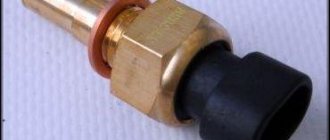
- 12 — engine temperature meter;
- 13 — idle system;
- 14 — detonation meter;
- 15 — tank purge system for collecting fuel vapors;
- 16 — crankshaft position meter;
- 17 — speed meter;
- 18 — air flow meter;
- 19 — lambda probe;
- 20 — throttle position angle meter;
- 21 — electric fuel pump complete with fuel level sensor;
- 22 — connection of the ignition system;
- 23 — control lamp;
- 24 — ignition switch;
- 25 - switching block;
- 26 — radiator cooling fan.
Since 2002, all VAZ 2109 began to be equipped only with engines with an injection system. The diagram shows the electrical wiring harness for the Bosch MP7.0 ECM (Euro 2 standards) on a 2003 car with a VAZ 2111 engine.
- 1 — four nozzles;
- 2 — spark plugs 2109;
- 3 — ignition distribution module;
- 4 - diagnostic connector, led into the car interior;
- 5 — Bosch controller connector;
- 6 — connector for the combination of lamps and instruments;
- 7 - main switching device of the system;
- 8 — fuse-link of the main device;
- 9 — controller for controlling the parameters of the fan on the cooling radiator;
- 10 — fan controller fuse;
- 11 — fuel pump control relay;
- 12 — fuel pump wiring fuse;
- 13 — intake air flow sensor;
- 14 — throttle opening angle sensor;
- 15 — engine temperature meter;
- 16 — regulator of idle speed parameters;
- 17 — sensor for measuring detonation in cylinders;
- 18 — crankshaft position sensor;
- 19 — lambda probe;
- 20 — immobilizer control unit;
- 21 — immobilizer status indicator;
- 22 — speed sensor;
- 23 - electric motor for driving the fuel pump; in the same module there is a device for measuring the remaining fuel in the tank;
- 24 — purge valve for the gasoline vapor recovery system;
- 25 — connector of the ignition system braid;
- 26 — instrument cluster with Check Engine indicator and warning lamp;
- 27 — ignition system start relay;
- 28 - lock;
- 29 — installation and switching block;
- 30 - cooling system fan.
Electrical component of the stove
Below is an electrical diagram for turning on the fan. For it to work, you need a temperature sensor, which is located in the radiator. When the coolant reaches a certain temperature, the sensor gives a signal and the fan turns on automatically.
- Mounting block.
- Ignition.
- Additional resistance (resistor).
- Motor.
- Button that controls the motor.
A – to the terminal with a plus sign “30” of the generator.
Some cars still have an old mounting block installed, in which case the fan is turned on via a relay.
Heating system elements
The stove diagram clearly shows the location of its main functional elements. It should be noted that the design of the stove on the VAZ-2108, 2109 and 21099 models is the same. Many car owners know that the heater in these models is not fully developed. As a result, the interior is not heated properly, so a decision is made to modify the stove with your own hands. Just in this case, it is important to know the design of the heater so as not to confuse anything.
The design of the stove of the VAZ-2109 car, whether it is a high panel or a low one, is absolutely identical. Therefore, the information presented will be useful to owners of this model with any instrument console.
Knowing the main points and what is located where, you can already try to independently deal with the problems that arise and fix the malfunctions that appear, while saving money and time on trips to the service station.
Source: remam.ru
Heater fan (interior heater) does not work
In this article we will look at the main points and reasons why the stove (stove fan) does not turn on.
How can you tell if the heater fan is not turning on? – very simple: with the car running, turn on the heater at 1-2-3 speeds. If no additional “noise” appears, then the fan does not turn on. I would like to note right away that if the fan does not turn on, for example, at speed 1-2, but does turn on at speed 3, then the problem is in the additional resistor or in the heater operating intensity switch.
Let's figure out how the stove turns on in theory. Pay attention to the picture:
- 44 – fan motor;
- 45 - additional resistor (used to regulate the speed of the electric motor, number 44);
- 46- position switch.
Why the stove motor does not work, the main reasons
1. The fuse has blown.
The simplest and at the same time the most unpleasant malfunction, because replacing the fuse is very simple, and at the same time, we do not know the reason why it blew. Let me remind you that if a fuse blows, it means there is a short circuit somewhere (short circuit). In this case, you need to go through the entire fuse circuit and look for the source of the short circuit.
What fuse goes to the stove?
A fuse F7 with a current of 30A is attached to the stove. This fuse is also responsible for the cigarette lighter, headlight washer motor, glove compartment light, and heated rear window. So, if a fuse blows, then in addition to the heater fan, the above-mentioned electrical elements of the car will stop working.
2. Poor contact in the mounting block.
Poor or oxidized contact in the mounting block is also a common disease. In this case, you need to move the block of flagella going to the mounting block.
3. The ignition relay is stuck.
If your stove is malfunctioning, for example, it only turns on when warm, then the problem is in the ignition relay.
It’s surprising, of course, how the ignition relay affects the operation of the stove, but the fact remains a fact. The relay needs to be replaced. By the way, it is located under the instrument panel in the center console.
4. The stove turns on only in position 3 of the switch.
If you encounter this situation, then you need to replace the additional resistor. The fact is that in positions 1 and 2 of the heater switch, current flows to the fan through an additional resistor, and in position 3 - directly to the fan. Therefore, the conclusion follows that the additional resistor is faulty. Additional heater resistor. Inspection, repair, replacement.
The device of the VAZ-21099 stove
There would be no question of any comfort while traveling in a VAZ-21099 car if the interior of this sedan were not equipped with a heating system. Moreover, ensuring a comfortable temperature in the cabin can be considered a secondary task, and the main one is heating the glass (windshield and side front doors) to ensure visibility in conditions of reduced temperatures.
The VAZ-21099 uses a heating system that is classic for all cars, in which the air is heated using an additional radiator of the cooling system installed in the cabin under the dashboard. Thanks to this location, it is possible to provide heating for several zones - airflow onto the windshields and side windows, under the feet and directly into the cabin itself.
To ensure the efficiency of the stove, it is necessary that the flow movement is not spontaneous (due to temperature changes), but forced. And for this purpose, the heating system is additionally equipped with an electric fan.
Design of the VAZ-21099 heater
And then everything is simple: the created flow passes through the radiator honeycombs, where heat exchange occurs, as a result, heat is transferred to the air, which then blows into the required zones through the air ducts.
The design of the VAZ-21099 stove includes several main components:
- stove body made of plastic;
- heating system radiator (connected to the cooling system);
- electric fan;
- air ducts;
- heater control mechanism.
This car used heaters of two modifications (old and new), which were slightly different in design, but their components were completely identical.
Housing, radiator, dampers
Thanks to the housing, the required redirection of heating is ensured, since the movement created by the fan motor is immediately fed into it, rather than being dissipated. The body of the VAZ 2109 stove itself consists of two halves, connected to each other with special brackets. To reduce flow losses, a seal is placed between its halves. Partitions are made inside both halves, which provide the correct direction.
There is also a niche inside this case into which the radiator is installed. Initially, the radiator was made of brass, but now it is almost always made of aluminum. The design of the stove radiator 2109 is identical to the main one (consists of two tanks, tubes through which coolant circulates, and plates that form honeycombs), but is significantly smaller in size.
Video: The stove in the VAZ 2108, 2109, 21099, 2110, 2111, 2112, 2113, 2114, 2115 HEATS poorly
Air is blown through the stove dampers, also installed inside the housing. These elements are movable, and thanks to them it is possible to close some and open other air ducts. There are three of them in total - the main one (heater control), an air duct that redirects between the foot area and the supply to the cabin, and a damper for supplying flow to the windshield.
Additional flaps are installed on the side and central deflectors. It turns out that by default, air from the housing constantly blows onto the deflectors and this is done so that the flow always has an exit. Thanks to the existing dampers, it is possible to provide simultaneous supply of hot air to several zones at once (the interior and the windshield or the windshield and the footwell area).
The main heater damper provides air flow to the radiator or bypasses it. This is all done because the heater also plays the role of a forced ventilation system for the interior. This allows for a supply of cool air in the summer. And to do this, you just need to redirect the movement bypassing the heat exchanger, and the supply of heated coolant to the radiator itself will stop. To disconnect the heat exchanger from the cooling system, a heater tap is used, which is located on the supply pipe in front of the radiator.
Heaters old and new
Finally, we note that the VAZ-21099 of different years of production used heaters with certain design features that related to the angle of the radiator and the location of the main damper.
In so-called old-style stoves (on cars before 1998), the radiator was installed almost vertically, and the main damper was located under the heat exchanger. There was a partition between the rear wall of the case and the radiator, which formed a channel that provided air supply down the case.
When the damper was open, the air flow moved through the radiator, where it was heated and supplied to the air ducts. In ventilation mode, the main damper closed the heat exchanger, forming, together with the front wall of the housing, another channel through which the flow went directly to the air ducts.
In the new model stoves (on cars produced since 1998), the radiator position angle was significantly smaller than on old heaters, which is believed to provide a larger contact area of the air flow for heat exchange.
The position of the main damper and its shape also changed (it became arched). It began to be located above the radiator. In the closed position (ventilation mode), the damper ensures air movement along the shortest path to the air ducts. In heating mode, it blocked the cold air supply channel to the air ducts and directed the flow down the housing, from where it went to the heat exchanger.
Source: avtocity365.ru
Troubleshooting the VAZ heater (stove) system
When the heater (stove) on VAZ cars stops working, especially in winter, you may lose the ability to drive a car altogether. Sometimes, after severe frost, it is impossible to clean the glass for viewing, and if the heater does not function, even getting to the service station will be problematic.
But, as a rule, the stove can be repaired on site without resorting to the services of specialists. Using the diagram and troubleshooting rules, you can do it yourself.
Principle of operation
The electrical circuit of the heater consists of:
- electric motor with fan (the fan blows hot air into the cabin, onto the windows and according to adjustments);
- power and speed selection buttons (on the classic VAZ 2101 - 2107, there are only two rotation speeds, on the VAZ 2108 - 2115 there are three speeds, on the VAZ 2110 - 2112 there are three speeds plus a ventilation mode);
- a set of additional resistances to ensure the required rotation speed of the heater fan (step-down, tungsten, turn coils);
- fuse and wiring;
Troubleshooting
Electrical system diagram of the VAZ heater (stove):
Connection diagram for the electric motor of the interior heater fan on a VAZ 2108, VAZ 2109, VAZ 21099:
1 – mounting block (fuse box);
2 - egnition lock;
3 – additional resistor (resistance);
4 – electric motor of the interior heater;
5 – heater motor switch button;
A – to the positive terminal “30” of the generator;
Repair of the electrical heating system of the VAZ interior
– the fan electric motor does not rotate at any position of the rotation speed switch: most likely, the electric motor itself has failed (the brushes have worn out), or there is no voltage at terminals 2 (ignition switch malfunction) and 4 connectors of the mounting block (fuse F4 has blown), it is also worth checking the mass of the engine itself (it should be no more than 3 ohms). The electric motor on the “classic” VAZ 2101 - 2107, as well as on the VAZ 2121, as well as on the VAZ 2121 “NIVA”: installed in the cabin, immediately behind the heating radiator; in VAZ 2108, 2109, 21099, 2113, 2114, 2115 - under the hood, in the compartment behind the engine shield; in VAZ 2110, 2111, 2112 and Priora 2170 - also under the hood, behind the plastic protection, on Kalina - in the cabin, under the dashboard.
– maximum fan speeds, according to the diagram, are without a switch, and if only the minimum and average speeds do not work for you, then the reason must be looked for in the speed switch button or in additional resistors (values in the diagram);
– sometimes, when you turn on the stove, you hear a very loud noise, high tones (squeaking) and there is no proper airflow. This indicates a malfunction of the heater electric motor itself (jamming of the impeller or armature bearings), in this case either replacement or disassembly and lubrication will help (not recommended, as it helps for a short time);
Modifications of VAZ-2109
VAZ-2109 . The basic model, which was produced from 1987 to 1997, was equipped with a 1.3-liter VAZ-2108 carburetor engine with a capacity of 64 horsepower.
VAZ-21091 . Modification of a car with a derated VAZ-21081 engine, 1.1 liter and 54 horsepower. It was mass-produced from 1987 to 1997.
VAZ-21093 . Modification of a car with a VAZ-21083 carburetor engine, 1.5 liters and 73.4 horsepower. Serially produced from 1988 to 2006.
VAZ-21093i . Modification with a VAZ-2111-80 injection engine, 1.5 liters. the first prototype appeared in 1994, mass production began in November 1998.
VAZ 21093-22 . Model made specifically for the Finnish market. It features improved interior trim, pre-installed alloy wheels and a new dashboard. The car was equipped with a 1.5 liter injection engine. Produced from 1995 to 1998.
VAZ-210934 . An all-wheel drive SUV with a VAZ-21093 body mounted on a Niva frame, on which the suspension, steering, engine, gearbox and transfer case from the same VAZ-2121 Niva model were already installed.
Autonomous heating control systems
Autonomous heating systems were installed on VAZ 2110, 2111, 2112, 2170 and others:
1 – electric motor of the heater fan;
2 – additional resistance (resistor);
3 – heater control controller;
4 – mounting block of fuses and relays;
5 – ignition switch (ignition switch);
6 – temperature sensor for air temperature in the cabin;
7 – recirculation switch (air intake from the street or the cabin);
8 – recirculation valve;
9 – micromotor gearbox for heater damper drive (cold or hot air);
A – to the instrument lighting switch;
B – to power supplies.
In such a system, if a malfunction occurs, the search must begin with:
- Checking fuses;
- Checking the control controller (it is necessary to check the supply voltage and the output control voltage);
- Switch and sensors (maximum speed mode must work);
- The electric motor itself (brushes, armature);
Construction and operation of the VAZ-2109 stove. Repair instructions.
Heating of the interior of any car is provided by air, which is heated in the heater radiator. The VAZ 2109 heater radiator is connected in parallel to the main radiator, which is part of the cooling system of a car engine.
The heater itself is secured with four nuts in the passenger compartment under the instrument panel to bolts that are welded to the air supply box. The air heated in the heater is directed through an air duct system into the passenger compartment. The air ducts are attached to the instrument panel from below and sealed with gaskets.
Place of the heater in the engine cooling system
The stove is part of a closed vacuum coolant circulation system. The main purpose of this system is engine cooling. Thus, the design of the VAZ 2109 stove both helps to heat the interior in cold weather and cools the cylinder block when the engine is running. The entire SOD consists of:
- cooling jackets;
- radiator;
- expansion tank;
- water pump;
- radiator fan;
- thermostat;
- heating radiator - VAZ 2109 stove.
When driving, atmospheric air passes through the air intake into the radiator, the pipes of which contain air that is too hot for the engine. These pipes are cooled by a fan, and the already cooled liquid again enters the cooling jacket (cylinder block and cylinder head) through the water pump. The stove in this antifreeze cycle performs the task of additionally removing hot liquid.
The VAZ 2109 heating fan maintains the desired air temperature in the cabin.
Features of the VAZ 2109 stove design
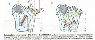
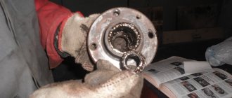
1. Heater casing mounting bracket; 2. Heater control damper; 3. Left heater casing; 4. Leg heating damper rod; 5. Radiator gasket; 6. Radiator; 7. Heater gasket; 8. Electric motor; 9. Fan shrouds; 10. Fan impeller; 11. Heating damper; 12. Heated windshield air duct; 13. Side nozzle air duct; 14. Side nozzle; 15. Central nozzle flap; 16. Blade pusher; 17. Blade axis; 18. Shoulder blade; 19. Lever for shutting off the central nozzle; 20. Windshield heating damper rod; 21. Lever for changing the direction of air flow; 22. Air heating control handle; 23. Windshield air supply handle; 24. Leg air supply handle; 25. Control lever bracket; 26. Bracket for fastening the rod shell; 27. Crane control rod; 28. Heater control damper rod; 29. Foot heating flap; 30. Axes of air heating control levers; 31. Screw clamp; 32. Heater valve; 33. Crane body; 34. Valve lever; 35. Hoses connecting the tap to the heater radiator; 36. Internal ventilation duct; 37. Windows for heating the feet of rear passengers; 38. Heater valve; 39. Driver's foot heating window; 40. Facing the central pillar; 41. Internal cavity of the central pillar; 42. Exhaust ventilation duct; 43. Upholstery of the central pillar; 44. Exhaust ventilation deflector lining; 45. Rubber valve; 46. Deflector housing; 47. Exhaust ventilation deflector; 48. I. Heater; 49.II. Heater operation diagram; 50.III. Heater valve; 51.IV. Interior exhaust ventilation
The stove consists of 2 plastic casings (right and left), which are connected to each other along the perimeter with fastening brackets. A special harness is placed into the grooves of the casings for sealing. The electric fan, which forces air into the passenger compartment, is secured with two screws on top of the heater. The design of the stove is made in such a way that the electric fan can be easily removed from the engine compartment.
An electric motor of type 45.3730 is attached to the fan casings, on the shaft of which an electric fan impeller with three rotation speeds is installed thanks to two resistor spirals. To obtain the required rotation speed of the impeller, an additional resistor is provided, attached to the hole in the stove casing on the left side with a screw.
The radiator for heating the supplied air is installed in the heater casings. It is attached to the right casing with three screws and sealed with a polyurethane foam gasket. It consists of:
- two rows of tubes,
- cooling plates,
- two plastic tanks.
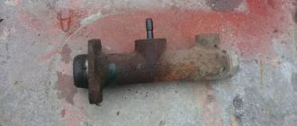
The heater tap, consisting of a housing with two pairs of pipes, is connected to the cooling system by rubber hoses. The cooling system pump circulates fluid through the radiator. On the supply line in the faucet body, a plate faucet valve is installed on the axis, which has a hole that allows coolant to pass through. The valve lever is connected by a rod to the handle lever, which can be used to control air heating. When you turn this lever, the hole in the valve will open the line so that fluid begins to flow into the radiator. Read more about replacing the heater valve here.
The stove is controlled using three handles, the levers of which are mounted on the axes of a plastic bracket attached to the instrument panel with four screws. The heating control handle acts on the valve lever through the rod and on the damper drive lever. When it moves completely to the right, both the valve and the damper are fully opened, and air is supplied by an electric fan through the radiator, where the heated coolant flows.
When the handle is in the middle position, the valve and damper are in intermediate positions; in this case, part of the air passes through the radiator, and part bypasses it. This reliably ensures the required degree of air heating at the moment. If the handle is placed in the extreme left position, the valve and control damper are completely closed, and the air supplied to the cabin is not heated.
The upper left handle, which regulates the air supply to the feet of the driver and passengers, is connected to the damper lever by a rod. When it is moved to the left, the foot warmer flap opens and air from the casings is directed into the windows. On the left and right sides, air is supplied to the feet of the driver and front passenger. Air is supplied to the feet of passengers in the rear seats through the interior ventilation duct.
The handle that regulates the air supply to the windshield is connected by a rod to the drive lever for the heated glass flap. It blocks or opens the way for air to reach the glass through the air duct.
To provide air supply to passengers and to blow the side windows, the car heater has right and left side nozzles, as well as 2 central nozzles. The body of each of them is equipped with a damper with a polyurethane foam seal. By opening or closing this damper using the lever, you can change the intensity of the air flow, and its direction can be changed using the lever, which rotates the nozzle with guides and blades to the desired position.
When the outside air temperature is minus 20°C, the stove provides the following temperature indicators at maximum heating mode:
- plus 20°С – in the interior of the VAZ 2109,
- plus 25°C – in the leg area.
The car has exhaust ventilation, which removes air from the passenger compartment. On the VAZ-2109 model it is located behind the body openings for the side windows. It is also carried out through the vacuum that occurs at the deflectors when the machine moves. Air is sucked out under the deflector linings from the rear of the cabin. He presses out the rubber valves, which prevent outside air from entering the cabin during crosswinds, and goes outside.
How to repair a VAZ 2109 stove
To ensure a comfortable temperature, a heater is installed in the car. The controller maintains the desired microclimate inside the car in the mode specified by the owner. The maximum deviation should not be more than 2 degrees Celsius. Deviation from these values indicates a malfunction.
This article explains how to repair the stove on a VAZ-2109 yourself.
The air supplied to the cabin is heated by a radiator built into the cooling system. It is then pumped by a fan through deflectors. A special regulator located on the panel is responsible for the intensity of heat supply.
Features of the heating system
Both in more modern models of the “nine” (where a high instrument panel is installed), and in earlier ones (where it is low), the ventilation is of the same type: supply and exhaust. Air enters through special openings installed in the windshield area by gravity or by force when the heater fan is running.
He leaves the cabin through the cracks in the doors. There are valves that allow air to escape outside, but prevent it from entering from the outside.
The heater is built into the engine cooling system and consists of:
- heater radiator installed near the main one;
- faucet;
- pump;
- fan
The stove itself is installed in the cabin under the instrument panel. Entering the radiator, the air is heated and then supplied to the cabin by an electric fan.
If this element needs to be removed, then this must be done from the engine compartment.
The heater tap is connected to two pairs of tubes extending from the cooling system. Directly in its body there is a valve that allows antifreeze to pass through. Its lever is driven by a rod using a handle located in the cabin.
The pump causes coolant to circulate in the radiator.
Opening (full) of the damper and tap occurs if the regulator is moved to the right all the way. At the same time, the fan forces air into the radiator, and the pump activates the movement of coolant.
The operation of the lower sleeves, which supply heat to the feet of people sitting in the cabin, is controlled by the upper regulator, which sets the damper in motion.
A normally operating stove allows you to maintain a comfortable 20 degrees of heat in the cabin at 20 degrees below zero.
Basic faults
As a rule, a heater failure occurs due to the fact that its electric motor stops functioning.
There are several reasons for this:
- combustion of the fuse link;
- breakage of the electrical circuit wires responsible for its operation;
- switch failure.
In the first case, the faulty protective device must be replaced.
If the new fuse burns out, you need to find out why this is happening. Most often this happens if there is damage to the insulation of the wires or their separation from the connecting terminals. The electrical circuit is tested with a multimeter, and if a defect is detected, it is eliminated. The regulator, in turn, usually does not work properly when its contacts burn out. A broken pusher also causes a similar result. The serviceability of this element is determined by measuring the voltage at its side contacts. Its presence when switching the toggle switch indicates operability. Otherwise, this unit will need to be replaced.
In addition, the motor itself may fail. The most common reasons are:
- breakage of armature winding wires;
- brushes sticking;
- collector oxidation.
If eliminating these causes does not correct the problem, then the engine is completely changed.
Sometimes a malfunction occurs due to a break in the wires supplying the mounting block or due to a burnout of the current-carrying track in it.
And finally, destruction of the resistor circuit may also occur - it is checked and the element that has become unusable is replaced with a serviceable one.
Repair
The procedure is performed after draining the antifreeze, in this order:
- from the interior side, disconnect 2 tubes leading to the faucet (you will need to loosen the fixing clamps);
- the remaining two are turned off in the engine compartment;
- unscrew the nuts on the faucet itself (from the bottom) and remove it (from the front);
- the rod is dismantled (you will need to disconnect the holder);
- the protective housing of the gearshift lever is removed;
- unscrew the screw in the gearbox tunnel and remove the floor covering;
- the ventilation hose is disconnected from the heater;
- the wires supplying them are removed from the resistor and the stove motor;
- To the right of the heater there are nuts securing it - they are unscrewed and the device itself is dismantled along with the control panel.
A faulty heater should be sent to a service center for repairs, since attempts to repair it on your own will most likely lead to undesirable consequences.
Other problems
Sometimes, when the stove is operating at full power, slightly warm air comes from the deflectors.
In this situation, adjustment of the dampers will be required. This is not difficult to do: you just need to arm yourself with pliers and patience. Using this tool, tighten the cable located near the gas pedal drive. Moving it to the right will open the damper and hot air will enter the cabin.
In addition, cold temperatures in the car often indicate a radiator failure. There is no need to repair this unit - it is replaced with a new one.
You should proceed as follows:
- the car is parked on a level surface;
- open the stove faucet and drain all the liquid there from the cooling system;
- dismantle the instrument panel.
The last point is performed in this order
- the negative terminal is disconnected from the battery;
- remove the drive cable and damper rod;
- remove all handles that control the heater and fan;
- pull out the protective cover;
- disconnect all connectors of wires leading to the panel;
- all instruments installed there are dismantled, as well as the steering wheel and ignition switch;
- Unscrew the screws holding the panel in place and remove it.
This gives access to the radiator. To remove it, you will need to disconnect the hoses from it and unscrew the fixing screws.
If the problem is only contamination of the radiator, then it will need to be cleaned. If a leak is detected, the entire assembly is replaced with a new one.
Features of operation and repair of the VAZ 2109 stove
Many owners of a domestic car of this brand know that the VAZ 2109’s heater does not heat well. As a result, the interior warms up poorly, and driving in such a car is not comfortable. In such cases, the stove is modified. Most often this is done within the framework of VAZ 2109 tuning with your own hands. Video and photo instructions for do-it-yourself tuning work can be found on the Internet. But sometimes it is enough to remove the VAZ 2109 stove and take it for repairs.
The operating procedure is described below.
- Loosen the clamps and disconnect the two hoses from the tap pipes under the instrument panel from inside the cabin.
- Loosen the clamps and disconnect the hoses in the engine compartment from the tap pipes.
- Unscrew the nuts securing the stove faucet.
- Remove the valve from the front panel.
- Remove the crane rod holder.
- Disconnect the rod from the crane lever.
- Remove the cover protecting the gear shift lever from the floor tunnel lining.
- Remove the floor covering.
- Unscrew the fastening screw at the rear of the floor covering tunnel.
- We remove the floor tunnel lining with a shift back.
- We remove the internal ventilation duct and disconnect it from the stove body.
- Disconnect the wires from the heater motor.
- Disconnect the wires from the resistor.
- Unscrew the mounting nuts on the right side of the heater.
- Unscrew the fastening nuts and remove the heater along with the control panel.
Electrical diagram of the stove and main faults
In the “nine”, the VAZ heating system operates using an electric drive. The instruction manual for the VAZ 2109 high panel shows an electrical diagram of the stove's operation. The interior heater connection diagram consists of:
- fan motor;
- the ignition switch, which turns on the stove;
- operating mode switch;
- additional resistor;
- fuse mounting block (fuse F4 is responsible for the stove in the “nine”).
When the VAZ 2109 stove does not heat well in the cabin, there can be a lot of reasons for this.
| Breaking | What causes this |
| If the electric motor does not function at low and high speeds. | Check the fuse - it may be burnt out. Wires and their contacts may be damaged or broken. Open the connection diagram and check the wiring. |
| It happens that the heater switch does not work well. | This may be caused by a stuck pusher or burnt contacts. We apply “plus” to the central terminal and check the voltage while the lever is operating. Perhaps the lever itself should be replaced. |
| A serious breakdown in which the VAZ 2109 stove does not heat is the failure of the electric motor. | The brushes may become stuck, the armature commutator may become dirty and oxidize. There could also be a problem with the wiring. We check, fix, if it doesn’t help, replace the engine. The circuit at the soldering points of the mounting block or the circuit of the additional resistor may also break. Again, using the electrical circuit, we carry out the test. |
If the engine armature rotates slowly, then the commutator has oxidized or the armature winding has shorted out, and the VAZ heater does not work. We check the current consumption, in case of a short circuit it will be more than 4.5 A. This is not normal. Also, the current may increase due to shaft jamming.
If there is noise from the electric motor, check to see if the engine impeller is jamming the deflector. It happens that the stove on a VAZ 2109 does not work due to overheating of the additional resistor. We check where the motor wires are pinched and fix the problem.
Such minor breakdowns need to be identified and resolved in a timely manner. If the heater is allowed to operate with a malfunction, the fan (stove motor) or the entire heater may fail. Then, in any case, you will need to either replace the heater motor or completely replace the heater on the VAZ 2109.
Conversion of the Lada 4×4 stove (installation of a fan from a VAZ 2108)
The stove on the VAZ 2121, 2131 has a number of advantages and disadvantages. One of them is associated with an electric fan, which not only blows weakly, but also makes a lot of noise and whistles during operation. Replacing it with a new type fan will solve only part of the problems. As practice shows, it is better to install an additional fan from the figure eight “snail” type.
The point of the modernization is to install on the Lada 4×4 an additional electric fan from the VAZ 2108, which will be located in the engine compartment inside the air intake, where it is normally positioned at figure eight. Let us remind you that the standard Lada 4×4 fan is located inside a plastic box in the cabin.
You will need: a figure-eight stove fan with a casing (catalog number: 2108-8101091).
The fan control can be left as standard, then there will be the least amount of modifications. Or use additional parts from the VAZ 2108:
- an additional heater resistor (article: 2108-8101081), which will need to be placed in the air intake next to the fan;
- fan speed switch (2108-3709608), which is mounted on a panel in the SUV interior.
The heater does not work on VAZ 2108, 2109, 21099 cars, reasons
Many owners of VAZ 2108, 2109, 21099 cars are familiar with the situation when, after turning on the electric motor of the heater fan (“stove”), it does not work or works, but only at the highest or lowest speed. Let's look at why this happens and what to do in such a situation.
Causes of failure of the heater fan electric motor - “stove”
— Heater speed switch is faulty
The simplest thing is that its back part (a round chip with several contacts) has moved away from vibration, or the contacts in it or on the switch itself have oxidized. The switch connection should be restored and the contacts should be cleaned. To do this you will have to disassemble part of the front panel.
— The “ground” in the electrical circuit for turning on the electric motor of the “stove” has disappeared
On VAZ 2108, 2109, 21099, the negative wire comes from the electric motor itself and is attached next to it to the car body. We clean the contact to restore ground.
— The wiring of the electrical circuit for turning on the fan motor is faulty
Perhaps the connecting block has simply come loose or the connections have oxidized. In the worst case, there is a “break” in some wire. Using the diagram we find the problem area.
— The electric motor itself is faulty
First of all, the brushes of the electric motor and its commutator (to which they are pressed) are suspect. Brushes may be worn out or damaged and may become stuck. The collector wears out or becomes dirty. In any case, it is necessary to remove the heater motor, disassemble it and check for a malfunction.
Revision instructions
Remove the air intake box (popularly called “boot”):
- In the interior, unscrew 4 nuts using a 10mm wrench;
- In the engine compartment, an assistant holds the bolts with the same key;
- Remove the air intake.
Remake the “boot” and install a fan in it:
- Cut off part of the plastic a little from the side so that the fan housing does not interfere with the hood lock;
- We cut off all the protruding parts of the fan mount and place it inside the “boot”;
- Secure the fan, securing its housing with sealant.
- We close the space around the fan nozzle with suitable material to prevent air outflow;
- We install the casing with the fan in place, laying the wires;
- We check that the hood closes without problems.
The result should be a design as shown in the video:
The damper can be left in place, but if it is removed, there will be no additional obstruction to the air flow into the cabin.
How to replace the heater motor
Very often, when a creaking noise appears when the stove is turned on, it indicates a malfunction of its motor or its imminent failure. In this case, you will need to replace the heater motor. There are also cases when you need to replace a heater fan; the operating principle for replacing a motor and a fan is very similar.
- Crosshead screwdriver.
- Ratchet with a head 10 mm in diameter.
- Flat screwdriver.
Replacing a VAZ stove fan is not a difficult job, the main thing is to clearly know what exactly you will do and in what order.
- Remove the plastic cover of the heating system; it is located in the engine compartment of the car and is held on by five bolts.
- Slide the heater motor protective cover; to do this you will need to remove the rubber band that acts as a hood seal.
- When removing the fan with the motor, unscrew the 2 mounting bolts that secure them.
- Then return to the cabin and find the positive wire plug under the steering wheel and unhook it.
- The next step is to unhook the negative wire; to do this, unscrew the fixing nut using a ratchet.
- Return to the engine compartment and remove the heater motor.
- Replace faulty parts.
- Reassemble everything in reverse order.
Try not to mess up anything with the connections of the electrical circuit, otherwise you will have to disassemble everything again.
It should be noted that any owner of a VAZ-2109 can handle the job, and the price is 1,500 rubles—about the cost of a new motor complete with a fan.