The cooling system plays an important role in the operation of the engine - its purpose is to cool the components of the power unit, which become very hot during its operation. One of the main elements of this system is the coolant temperature sensor. You can learn more about its purpose, operating principle and replacement from this article.
Characteristics of the coolant temperature sensor
So, what is the main or additional coolant temperature sensor (DTOZH), what is its device, what functions does the element installed in the cooling system perform? First, we suggest finding out where the engine temperature sensor is located and what functions it performs.
Purpose and location
The TOZ sensor is a device used to support the optimal operation of the main components of the vehicle. This regulator allows you to quickly warm up the engine and also prevent it from overheating. The TOZh sensor is small in size, however, its importance cannot be denied. If the coolant sensor is faulty for some reason, this can lead to more serious consequences. Especially if the malfunction of the coolant temperature sensor is detected untimely.
Installation location of the regulator in Lada
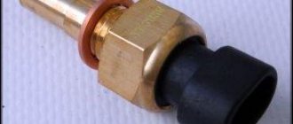
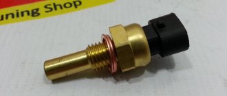
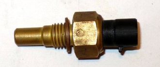
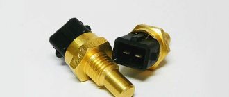
The regulator itself is a fairly small device, made in a plastic case and equipped with a steel thread. If you are wondering where the coolant temperature sensor is located, we will now give you the answer. Using a thread, the device can be installed and connected to the outlet line of the BC head by simply screwing into it.
Depending on the design features of the car, it can also stand next to the thermostat housing or directly on the body. The car temperature sensor must be positioned in such a way that it is in direct contact with the consumable. Accordingly, if the level of antifreeze in the system is too low, the sensor readings may be incorrect.
Some car enthusiasts confuse the concepts; for them, DTOZH is the same as a coolant level sensor or a temperature and air pressure sensor. This is fundamentally wrong, since the coolant level sensor is used to determine the volume of consumables. Its role is not as significant as that of the DTOZH. Moreover, the coolant level sensor is located in the coolant expansion tank. Depending on the design features of the car, two DTOZH can be used - one of them determines the temperature at the outlet of the engine, and the other - from the radiator.
Design and principle of operation
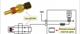
How does the coolant temperature sensor work? We’ve sorted out the location and purpose, now let’s look at the design and principle of operation. The main structural component is a resistor thermistor, which changes the resistance of the coolant temperature sensor in accordance with the temperature conditions. This component is installed in a threaded steel housing, to which is connected a plastic tail section, where the contacts used to connect the wiring are located. The connection diagram for the coolant temperature sensor is quite simple. One contact of the regulator is a plus, it connects to the ECU, and the second is a minus, it connects to ground (the author of the video is the channel Valerii1986).
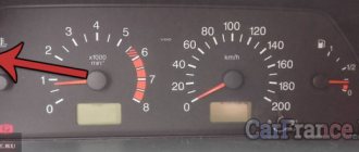
For the device to work properly, it needs 5 volts of power, which is supplied from the ECU using a resistor with a constant resistance. Since the thermistor itself has a negative coefficient, its resistance level will decrease as the temperature increases. Accordingly, the voltage level that powers the regulator will drop. In accordance with the drop in this parameter, the ECU calculates the temperature of the engine, and the readings are displayed on the dashboard. A high signal level of the coolant temperature sensor, which the driver can find out from the controller with a signal arrow on the dashboard, may indicate a malfunction.
Infrared sensor design
One of its main elements is a pyroelectric detector, which consists of a pair of rectangular crystals that respond to infrared radiation within a certain distance. With a uniform background of space, currents of the same magnitude are induced in the crystals. When a heat source appears in a sector of one of the crystals, a difference in current values occurs. This pulse is amplified, converted into a digital signal and sent to actuators, relays with a group of closing contacts.
Appearance and schematic display of a pyroelectric sensor
For more efficient operation, a Fresnel lens is installed in front of the pyrotransmitter at a distance of 1.5–2.5 cm, which focuses infrared radiation on the crystals. More precisely, it is an optical system from a group of lenses of 20–60 pieces, milky or gray in color, made of plastic. The system has a spherical shape, thereby expanding the field of view of the sensor.
Electrical circuit and types of motion sensor designs
The sensor, which is located in the figure on the left, is recommended to be hung on the ceiling in the center of a large room with several entrances. An overview of such a device is 360˚, three pyroelements with a sector of 120˚ each.
Board with four pyroelements, 360 degree view of the sensor
The second sensor has a horizontal viewing sector of no more than 180 ̊, it is usually placed in the direction of a door or external gate, fixed to the walls of buildings, it has the ability to change the direction of the vertical viewing sector.
Symptoms of a controller malfunction
Now let's look at the signs of a malfunctioning coolant temperature sensor. Overall, this controller is quite reliable because its design is simple. However, malfunctions may occur during the operation of this device. As a rule, they are caused by a violation of calibration, which, in turn, affects the incorrect operation of the ECU, since this unit performs some of the options taking into account the temperature conditions of the motor. If the temperature gauge does not work, then the primary sign of its failure is the failure of the fan to turn on.
However, this symptom is not fundamental; more precisely, I can say the following symptoms about the failure of the regulator:
- increased fuel consumption;
- increased engine speed when idling;
- if the sensor does not work, this can also lead to detonation in the engine;
- there is a possibility that the engine will be difficult to start when hot;
- engine overheating (video author: Denis Tsirkunov).
You need to be most careful with the last symptom, since this symptom can lead to damage to the block head. In older cars, the controller on the dashboard allows you to determine the malfunction - if you see that the device’s arrow has moved beyond the standard mark, you need to stop the car and identify the cause of the problem. In more modern cars, a corresponding message may appear on the on-board computer screen if the engine overheats or the DTO fails. As practice shows, replacing the coolant temperature sensor is usually done in case of oxidation or damage to its contacts; the reason may also be a broken wiring.
Air consumption in a car
This device measures the amount of heat that is picked up by the air flow as it enters the intake manifold. Taking into account these data, it determines the volume of air in kilograms per hour. One of the elements of the device is located in front of the car’s air filter, so the accuracy of the readings depends on the cleanliness of this filter element.
Loss of power and malfunctions during engine operation are the main signs of failure of this sensor.
Self-diagnosis methods
How to check the coolant temperature sensor? Before removing and replacing the sensor, you need to make sure that it is the problem that is causing the problem. Checking the coolant temperature sensor can be done at home; there are several ways to do this.
First, let's describe the first method - how to check a temperature sensor by placing it in water:
- First, you need to place the thermometer in a container of cold water. Alternatively, you can use a kettle. It is advisable to use an electronic device, since you will need to measure the temperature at elevated temperatures.
- Then you need to connect a tester to the controller - a multimeter, which needs to be set to resistance measurement mode.
- Then the DTOZH itself is installed in the kettle.
- Take readings from the regulator and write them down on a piece of paper.
- Next, the container is placed on the stove and heated, while you must take the resistance values of the DTOZH when reaching the main heating points - 15, 15, 20, 25 degrees, etc.
- After this, it is necessary to compare the obtained values with those given in the table.
Photo gallery “DIY diagnostics”
1. Regulator resistance measurement
2. Table of dependence of the DTOZ parameters
In the event that the readings differ from the most optimal, this indicates a breakdown of the regulator, and accordingly, it will need to be changed. There is another diagnostic option. How to check the coolant temperature gauge without a thermometer?
The principle of this method is that when heated, the temperature of the water will be a maximum of 100 degrees, no more. Therefore, this point can be taken as the main value and the resistance can be measured. When the water boils, the regulator's resistance level should be about 177 ohms. If we take into account the errors, then this figure can be approximately 190-210 Ohms.
Actions of the car owner in case of sensor failure
If the regulator is not working correctly, then you have several options:
- make sure that the problem is not a broken wiring; if so, then the damaged circuit must be restored;
- check the contacts for oxidation - to do this, the power wire must be disconnected and the contacts cleaned;
- if these actions do not help, then the only solution is replacement.
How to troubleshoot an absolute pressure sensor
Before any testing, check the appearance of the sensor. Start by checking the connections and wiring for any damage, such as melted or cracked wires, and make sure there are no loose connections. Disconnect the sensor and check the contacts; they must be straight and clean, without signs of corrosion or bending. Next, check the hose (if there is one) connecting the sensor to the intake manifold for any signs of damage and for a tight connection to the sensor. Finally, look inside the hose to make sure it is not dirty.
If everything is fine here, then you can test the sensor using a digital multimeter set to the 20V limit and a vacuum pump.
- With the battery connected and the engine off, connect one multimeter probe to the negative terminal of the battery and the other to the positive terminal and check the battery voltage. It should be around 12.6 Volts.
- Refer to the manufacturer's service manual to identify the signal pin, ground, and 5-volt power supply and check them.
- Turn on the ignition without starting the engine. The multimeter should (typically) read about 5 volts for a 5 volt supply, a steady 0 volts for the ground wire, and 4.0 to 4.5 volts for the signal wire on a non-turbo car, or 2.0 to 2.5 Volt for cars with turbocharging. These are values for atmospheric pressure "at sea level". Refer to factory service information for exact specifications for your vehicle.
- Start the engine after connecting to the signal wire. The multimeter should show a voltage of 0.3 to 0.5 Volts for a non-turbocharged car, and 0.2 to 0.5 Volts for turbocharged models (the value depends on the load on the engine).
- Turn off the engine, but do not turn off the ignition.
- Under the hood, disconnect the MAP sensor from the intake port only.
- Connect a hand vacuum pump and measure the current voltage on the signal wire.
- Apply vacuum to the sensor using a vacuum pump.
- The voltage from the sensor should drop in proportion to the increase in vacuum.
If your test voltage is very different from the specified values or the voltage change is unstable, then the manifold pressure sensor is faulty and must be replaced.
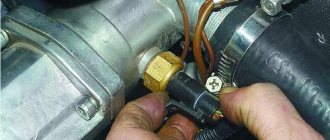
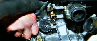
Instructions for removing, replacing and connecting DTOZH
Dismantling the TOZh controller
How to change the coolant temperature sensor with your own hands? Before replacing the controller, you need to know exactly where it is located in your car; you can use the service book to clarify.
The replacement process looks like this:
- Open the hood of the car and unscrew the filler cap of the antifreeze reservoir.
- Then you need to place a container under the refrigerant drain hole, and unscrew the hole cover.
- Disconnect the wire that powers the controller.
- The controller itself, depending on the design features of the car, can be fixed with a latch, a clamp, or screwed in with a thread. Dismantle the device.
- Next, the coolant temperature sensor is installed. Before installation, the replaced device can be treated with a sealant, in particular, we are talking about contacting surfaces.
- Refill with antifreeze.
Price issue
The cost of the device is determined by the model of the car in which it will be used, as well as by the manufacturer. JP GROUP regulators cost about 200 rubles, from the manufacturer BERU - around 350 rubles, from the manufacturer Hella - approximately 700 rubles. Prices are average, excluding car model.
Design and principles of operation of the sensor
The crankshaft position sensor (CPS) device includes:
- Nylon frame;
- Steel magnetic core;
- winding made of thin copper wire;
- Insulation (enamel or resin).
The sensor is designed to create synchronized operation of fuel injectors and the ignition system. Faulty operation of this element leads to unstable or absent fuel supply, fraught with stopping the engine and the inability to start it . The operation of the sensor allows the computer (microcontroller) to determine the position of the pistons in the cylinders. The crankshaft has a gear with two missing teeth. During the movement of the shaft, the teeth of the wheel pass near the sensor, thereby distorting its magnetic field and pulses are formed in the inductance coil of the sensor. The absence of two teeth is the starting or zero point for the computer to determine the initial position of the crankshaft. The computer counts the number of pulses that come from the sensor and determines what position the crankshaft is in, and, based on the position of the crankshaft, calculates the time for the fuel injectors and ignition system to fire.
Conclusion
When the throttle position sensor has signs of malfunction that become obvious to the naked eye, in most cases the device must be replaced with another, working device. You should not delay repairing the vehicle: this device has a direct impact on the operation of the engine. If the problem is left unchecked, it can lead to a sharp deterioration in the quality of the fuel-air mixture, which is formed due to the action of the throttle valve. The malfunction of these spare parts negatively affects the operation of the entire internal combustion engine system, which in 70% of cases leads to the need to replace the engine with a new unit.
Purpose of the throttle position sensor
This sensor transmits data to the electronic engine control unit about the position of the bypass valve in a certain time period. The operation of this unit is based on the interaction of AC and DC converters.
The highest value of the total resistance of the converters is at the level of 8 ohms. The design of the remote sensing sensor has three contacts. The first and second contacts receive a current of about 5 V, and the third contact is connected to the controller and performs a signaling function.
DPD3 is located on the throttle body. The device receives signals about the opening and closing of the passage channel. The resistance index of the part changes to satisfy the following conditions:
- when the damper is open, the voltage on the third contact will exceed 4 V;
- if the air passage is blocked by the remote control damper, then at the 3rd contact the current does not exceed 0.7 V.
The device controls all fluctuations in contact voltage and thus regulates the supply of fuel necessary for the formation of the air-fuel mixture.
Due to a malfunction of the sensor, the voltage reading most often goes beyond the established limits. This leads to disruption of the normal operation of the internal combustion engine, which can ultimately lead to breakdown of the unit.
We recommend
“Expansion tank cap: we understand the design and purpose” More
Important: a malfunction of the sensor often causes a malfunction of the gearbox. Every car owner understands that restoring an engine and transmission is a process that requires a large investment of time and money. If symptoms indicating a breakdown appear, it is necessary to carry out a diagnosis.
How DPKV works and how it works
Before we talk about repair and diagnostics of the crankshaft position sensor, we should talk about what these sensors generally are and what the operating principle of such devices is. So, there are three main types of crankshaft position sensors:
- magnetic induction;
- optical;
- Hall sensors;
An electrical voltage is induced in a magnetic sensor when the teeth of the timing disk pass through the magnetic field that surrounds the sensor. Such a sensor is quite simple, and most importantly, it does not require additional electricity to operate.
In an optical sensor, the teeth of the timing disk interrupt the light beam as they pass between the LED and the light-sensing element. And here, for the sensor to work, a certain minimum of electricity is needed, otherwise the diode simply will not light.
Hall sensors are based on the effect of the same name and operate on the principle that an alternating magnetic field intersects the synchronization disk with the constant field of the sensor.
Based on the DPKV readings, the position of the crankshaft is determined, as well as its rotation speed. Thanks to this, it is possible to synchronize the operation of the engine in general and the fuel supply with the ignition system in particular.