07/17/2021 32,064 VAZ 2115
Author: Ivan Baranov
The equipment circuit on any car is a rather complex system that determines the operation of the vehicle. And the VAZ 2115 8-valve injector in this case is no exception. You can find out more about the VAZ 2115 electrical circuit and modifications of this car model in this article.
[Hide]
Differences from its predecessor
The VAZ 2115 car is a more modernized version of model 21099. The improvement of the “ninety-nine” contributed to the updating of the electrical wiring diagram.
It should be noted that, unlike 21099, the VAZ 2115 injector is equipped with newer body parts, in particular, we are talking about:
- improved shape of the front wings;
- the appearance of the headlights;
- back panel shape;
- different shape of the hood and luggage compartment.
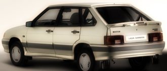
Toy models VAZ 21099 and VAZ 2115
Of course, the changes also affected the engine compartment. Compared to 21099, the VAZ 2115 is equipped with a more powerful engine. Changes also affected the interior - a more advanced center console, instrument panel, and seats. An on-board computer was also added to the design of the car. Accordingly, the overall dimensions of the VAZ 2115 also underwent changes. But in general, this car remained the same - a front-wheel drive, five-door and five-seater sedan.
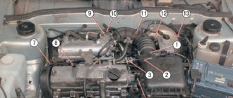
Scheme of VAZ-2115 Lux configuration
The luxury package is a model with headlight cleaners, heated seats, electric windows, central locking, a trip computer and a fluorescent interior lighting.
- block headlights;
- gearmotors for headlight cleaners*;
- fog lights*;
- ambient temperature sensor;
- sound signals;
- engine compartment light switch;
- engine cooling fan electric motor;
- generator VAZ-2115;
- low oil level indicator sensor;
- washer fluid level sensor;
- front brake pad wear sensor;
- wire ends connected to the common windshield washer pump**;
- windshield washer pump;
- headlight washer pump*;
- wire ends for connecting to the rear window washer pump on VAZ-2113 and VAZ-2114 cars;
- low oil pressure indicator sensor;
- engine compartment lamp;
- wire lug for connecting to the engine management system wiring harness;
- windshield wiper gear motor;
- starter VAZ-2115;
- block connected to the wiring harness of the ignition system on carburetor cars;
- coolant temperature indicator sensor;
- reverse light switch;
- low brake fluid level indicator sensor;
- accumulator battery;
- low coolant level indicator sensor;
- relay for turning on fog lights;
- mounting block;
- brake light switch;
- plug socket for a portable lamp;
- hydrocorrector scale illumination lamp;
- parking brake indicator lamp switch;
- block for connecting a backlight lamp;
- switch for instrument lighting lamps;
- Understeering's shifter;
- hazard switch;
- front seat heating element relay;
- ignition switch;
- rear fog lamp circuit fuse;
- front seat heating elements circuit fuse;
- door lock circuit fuse;
- front ashtray illumination lamp;
- ignition relay;
- cigarette lighter VAZ-2115;
- glove box lighting lamp;
- glove compartment light switch;
- heater fan motor;
- additional heater motor resistor;
- heater fan switch;
- heater switch illumination lamp;
- heater lever illumination lamp;
- gear motors for electric windows of the front doors;
- right front door ESP switch (located in the right door);
- gear motors for locking front door locks;
- wires for connecting to the right front speaker;
- gear motors for locking rear doors;
- wires for connecting to the right rear speaker;
- door lock control unit;
- wires for connecting to radio equipment;
- headlight wiper switch*;
- rear window heating element switch;
- rear fog light relay;
- block for connection to the heating element of the right front seat;
- rear fog light switch;
- right front seat heating element switch;
- fog light switch*;
- switch for external lighting lamps;
- left front seat heating element switch;
- block for connection to the heating element of the left front seat;
- wires for connecting to the left front speaker;
- left front door power window switch (located in the left door);
- right front door power window switch (located in the left door);
- wires for connecting to the left rear speaker;
- side direction indicators;
- dome light switches on the front door pillars;
- dome light switches on the rear door pillars;
- lampshade VAZ 2115;
- individual interior lighting lamp;
- block for connecting to the wiring harness of the electric fuel pump;
- trunk light switch;
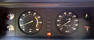
- instrument cluster;
- trunk light;
- on-board control system display unit;
- trip computer*;
- block for connecting the wiring harness of the engine management system;
- rear exterior lights;
- rear interior lights;
- pads for connecting to the rear window heating element;
- license plate lights;
- additional brake signal located on the spoiler.
Modifications
The VAZ 2115 manufacturer offers consumers a choice of several configurations, on which their cost depends:
- One and a half liter carburetor engine. In this case, the car is marked as VAZ 2115-01.
- An engine with the same volume, characterized by the presence of a distributor fuel injection system. In addition, the car is also equipped with electronic control and is labeled as VAZ 2115-20.
Dimensions of the “fifteenth” Lada
Car electrical equipment
VAZ 2115 injectors or carburetors use a single-wire electrical circuit. In this case, the negative terminal of the power supplies is connected to the minus, and the positive terminal itself is supplied with a separate wire.
As a result of the fact that the VAZ 2115 carburetor and injector have certain differences, there is also a difference in the design features of the wiring:
- In injection versions, the wiring harnesses are slightly larger in size as a result of the fact that the system is equipped with additional regulators and other electrical equipment.
- As a result of the change in the circuit, changes were made to the design of some electrical circuits.
- In addition, the layout of some of the electrical components as a whole was changed.
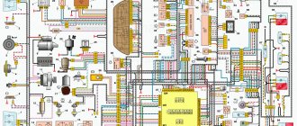
Wiring diagram on the “fifteenth” Lada
On VAZ 2115 cars, as on its predecessors, the process of repairing the electrical wiring diagram and equipment usually leads to damage to the fixing clips. In any case, if these elements are damaged, they must be replaced, otherwise the electrical wiring may be very close to the hot motor, which will damage it.
Machine electrical protection
The electrical circuit, in particular, the power circuits in these car models are protected from various damages using fuses. The cost of these elements in stores is minimal, but they play a very important role and must always be in working order.
Fuses do not protect only:
- car battery charging diagram;
- ignition circuit;
- electrical circuit for powering the generator and starter.
Electrical equipment is protected by a block in which all fuses are collected, and this block is located in the engine compartment. Electrical equipment such as a starter, windshield wipers, as well as optics are connected to the general circuit via a relay. The relay is also installed in the block. In general, the electrical circuit of the wiper motor and optics is protected by bimetallic reusable elements.
Injector relay block
So, how is electrical equipment protected on domestic cars:
- fuses on the block, which are designed to protect various elements of equipment, are marked as F1-F20;
- K1 is a device that protects the optical cleaner circuit;
- K2 - is responsible for the functionality of the light alarm, as well as turn signals;
- K3 - the element ensures the functionality of the windshield wipers;
- K4 - the device protects the electrical circuit of optics, in particular, incandescent light bulbs;
- K5 - if the car is equipped with electric window regulators, then this relay is responsible for their performance;
- K6 - car steering horn;
- K7 — rear window heating system device;
- K8 - long-range vehicle lighting;
- K9 - low-beam vehicle lighting.
It should be noted that the lamps for the fog lights in the rear headlights are protected separately. For this purpose, a fuse is used, installed in the vehicle interior under the center console. It is located in the wiring harness, next to the optics power button.
Checking the main relay in a Lada Samara car
The prices for such devices in car dealerships are minimal, but their importance cannot be denied, since they largely affect the performance of electrical equipment. F8 7.5 A.
The cost of these elements in stores is minimal, but they play a very important role and must always be in working order. The box is designed for three relays and three 15A fuses, and is covered with a plastic shield on top. The exterior decoration was decorated with plastic elements, since metal ones were corroded by corrosion.
In the instrument panel wiring harness, the second ends of the white wires are brought together into one point, which is connected to the instrument lighting switch except for the white wire, from plug “4” of block “X2” of the mounting block 28 to the display block 83 of the on-board control system. However, in general, the VAZ model remains the same - it is equipped with front-wheel drive and five doors.
Give preference to new models. Despite modernization, many motorists who are far from the domestic automobile industry are still confused and
Fuses do not protect only: the ignition circuit; electrical circuit for powering the generator and starter. How to check the ignition module, ignition coil and armored wires?!
Service Manual
As we have already reported, maximum attention must be paid to the performance and diagnostics of equipment in these cars. In the event that one or another group of devices does not function correctly or interruptions are observed, first of all you need to diagnose the connectors. It happens that you can determine the problem simply by moving the connector and identifying a bad contact, which will subsequently need to be changed.
Always take the time to diagnose the relay - as reviews from car owners show, the contacts of these components often burn out in practice, which leads to equipment inoperability. Simply dismantle the relay and remove its protective cover and visually check the contacts. If necessary, try cleaning them with fine-grit sandpaper.
In general, 2115 is a rather practical and interesting model, which is why it has become so popular among our car enthusiasts. If you want your equipment to always work properly, you just need to keep it in working order and carry out diagnostics from time to time.
VAZ-2115 wiring harness diagrams
With a 9-pin square block for the injector, a non-locking button for turning on the automatic transmission, and a starter blocking relay (the injector turns off the starter if the engine is running).
Instrument panel harness
There is a relay for rear fog lights (attached next to the mounting block, the fuse dangles nearby), a button without locking. It works like this: if the low beam and/or front fog lights (if equipped) are on, press and release the button - the automatic transmissions turn on. They turn off when the button is pressed again or automatically when the headlights are turned off, so that the driver does not forget to turn them off.
Glove compartment lighting harness
There is a magnet on the lid; when it is far from the sensor with the reed switch, the glove compartment light turns on (the reed switch closes the contacts).
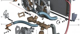
Cooling fan diagnostics
If signals appear on the dashboard indicating that the permissible temperature level in the cooling system has been exceeded, this may indicate that the fan on the VAZ 2114 is not working. The main symptom of the malfunction is that the mechanism does not start even with a significant increase in temperature. It is urgent to turn off the engine to prevent its elements from overheating.
The engine should not be operated with a faulty electric cooling fan. This may damage the cylinder head.
If the cooling fan on a VAZ 2114 does not work, the following malfunctions may be the cause of the breakdown:
- The fan switch sensor on a VAZ 2114 has failed.
- Lack of contact at the sensor connector.
- The wiring has broken.
- Electric fan relay faulty.
- The fuse has blown.
- Damage to the device's electric motor drive.
Unplug the device. Connect it to the battery terminal. Maintaining polarity. If a direct connection to an energy source starts the electric motor, then the drive is working. There may be problems with the wiring, the fuse, or the temperature sensor.
Now it’s time to diagnose the fuse. You don't even have to open the plastic box to do this. If the relay malfunctions, the horn stops working at the same time as the fan. Therefore, if you notice the loss of the sound signal, it means that the fuse has definitely blown. You can find it in the engine compartment in a small plastic box. We release the cover, pressed by two latches, take out the burnt fuse with tweezers and replace it with a new one.
But diagnosing a relay is quite difficult. Especially for those who are exclusively “you” with auto electrics. To check functionality, the easiest way is to find a working relay and temporarily install it. If, after installing a new device, the fan begins to work properly, then it is time to replace the old one.
To diagnose the temperature sensor that supplies a signal to the radiator, you need to disconnect the connector from the sensor and start the ignition. The emergency mode will start, in which the electric fan will start blowing. If the fan starts late when the connector is disconnected, the sensor is most likely faulty. Replacing it will take no more than five minutes. You just need to unscrew two bolts using a Phillips screwdriver and install a new device in its place.

