14.13. Watch
MODELS BEFORE 1992
| EXECUTION ORDER |
| 1. Disconnect the negative cable from the battery. | |
| 2. Remove the three locking plates located under the ventilation system nozzles and covering the screws securing the instrument cluster panel. | |
| 3. Unscrew the screws and lift the instrument cluster panel. | |
| 4. At the back of the clock, loosen the fastening brackets and remove the clock from the instrument panel. | |
| 1. Disconnect the negative cable from the battery. | |
| 2. Remove the center console. | |
| 3. Unscrew the two screws located at the bottom of the ashtray socket. | |
| 4. Remove the radio receiver. | |
| 5. Unscrew the two fastening screws from the top of the radio frame. | |
| 6. Using a thin screwdriver, remove the decorative plate from the upper corner of the frame of the central nozzles of the ventilation system and unscrew the exposed screw. | |
| 7. Unscrew the four screws securing the trim located under the heating and ventilation control panel. Two screws are accessible from the front and two from the bottom. | |
| 8. To access the instrument panel mounting screw, use a thin screwdriver to remove the switches located under the central nozzles of the ventilation and heating system. | |
| 11. Unscrew the two fastening screws and remove the clock from the panel. |
Installation is carried out in the reverse order of removal.
The electromechanical clock on the VAZ-2107 car failed (marking on the case AKCH-1, with a second hand). After flaring the decorative metal ring, the watch was disassembled and the condition of the components was analyzed. The mechanical part of the watch (gearbox) and the engine turned out to be in good working order. The electronic unit has failed. The reason is the failure of an unpackaged microcircuit placed on a printed circuit board and filled with compound.
Since it naturally turned out to be impossible to repair the watch by replacing the microcircuit, it was decided to develop an electronic unit to replace the failed one. The diagram of this unit is shown in Fig. 1.
The electronic unit is based on the PIC12F675 microcontroller. Clock frequency
The microcontroller is determined by the quartz resonator and capacitors C4 and C5 connected to it. The microcontroller is powered from a 12 V battery through a linear voltage regulator DA1 with filter capacitors C1-SZ. The electronic unit includes a switching bridge formed by two pairs of transistors of different conductivity VT1-VT2 and VT3-VT4. The clock motor M1 is connected to the bridge outputs. The bridge is controlled by a microcontroller through its pins 6 and 7 and resistors R1-R4.
The microcontroller program, launched when voltage is applied to it, configures pins 5-7 as output. Pin 4 of the microcontroller is a free input. To avoid the appearance of a floating voltage on it and an increase in the current consumed by the device due to this, it is connected to a common wire. The microcontroller program initializes the built-in
The TMR1 timer module is installed in the microcontroller in such a way as to receive interrupts from it every second. In a program activated by interrupts, outputs 6 and 7 of the microcontroller are transferred to opposite states: when output 6 is set to “0”, output 7 is set to “1”. After a second, the output states change to the opposite. One of the inputs of the clock motor is connected through bridge transistors to the output of the stabilizer, and the other is connected to the common wire, i.e. The polarity of the motor connection is reversed every second. This is exactly what is necessary for its normal operation.
The tailoring text is shown in Table 1. The required configuration word (3F88) is already specified in the program text.
The printed circuit board of the electronic unit was not developed. For assembly, a breadboard was used, installed in place of the failed electronic unit. Capacitors, resistors - any small ones.
Instead of the PIC12F675 microcontroller, the simpler PIC12F629 can be used with the same firmware (the author did not have this at his disposal).
A correctly assembled watch starts working immediately. You may need to adjust their accuracy. Watch the clock for several days. If the timing accuracy is unsatisfactory, select the capacitance of capacitor C5: as the capacitance decreases, the clock speeds up, and as the capacitance increases, it slows down. Another option for adjusting the precision of the stroke without selecting the capacitor capacitance is to change the microcontroller program. To adjust the progress in this way, it is necessary to find in the source text of the program the place where the initial code is entered into the timer register, change it, translate it in the MPLAB environment and add new firmware to the microcontroller.
The HEX file and the original one can be requested from the author, the editor, or taken from the CDU20 disk (folder “HEX”) purchased no earlier than the month of publication of this journal.
The work applies exclusively to the idle speed of the VAZ 2106. The setting does not affect other engine operating modes. There are two screws for regulation: a large one for the number of revolutions and a small one for the quality of the mixture.
Before starting work, make sure that the ignition system is working properly. Adjust or repair it if necessary. The engine must also be in good working order.
Tachometer malfunctions
Despite the fact that the TX-193 tachometer is considered quite reliable, it also has malfunctions. Their signs are:
- lack of response of the needle to changes in engine speed;
- chaotic movement of the arrow up and down, regardless of the engine operating mode;
- obvious underestimation or overestimation of readings.
Find out the reasons for the VAZ 2106 engine malfunction: https://bumper.guru/klassicheskie-modeli-vaz/poleznoe/ne-zavoditsya-vaz-2106.html
What kind of breakdowns do the listed signs indicate?
The arrow does not respond to measuring the number of revolutions
Usually, the lack of response from the arrow is due to a broken contact in the connectors of the main wires of its connection, or damage to the wiring of the circuit. The first step is:
- Inspect the fastening of the conductor in brown insulation to terminal “K” on the ignition coil. If you detect poor contact, traces of oxidation, burning of a wire or terminal, fix the problem by cleaning the problem areas, treating them with anti-corrosion liquid, and tightening the fastening nut.
- Check the reliability of the connection of the black and white wire to the vehicle ground. If contact is broken, clean the wire and the surface to which it is attached.
- Using a tester, determine whether voltage is supplied to the red wire when the ignition is on. If there is no voltage, check the serviceability of fuse F-9, which is responsible for the integrity of the instrument panel circuit, as well as the condition of the ignition switch contacts.
- Disassemble the instrument panel and check the connections of the contacts in the tachometer wiring harness block. “Ring” all the wires going to the device with a tester.
Video: tachometer needle does not respond to engine speed
The tachometer needle jumps chaotically
Jumps in the TX-193 needle in most cases are also a symptom of malfunctions associated with its electrical circuit. The reasons for this behavior of the device may be:
- lack of good contact at the negative terminal of the battery;
- oxidation or burning of the brown wire on the ignition coil;
- burning or wear of the contacts of the ignition distributor cap or slider;
- wear of the distributor shaft bearing;
- shorting the red wire powering the device to vehicle ground;
- malfunction of the crankshaft position sensor (for injection engines).
A similar problem is solved by stripping the contacts, replacing the ignition distributor cap, slider, support bearing, restoring the integrity of the insulation of the device’s supply wire, and replacing the crankshaft sensor.
Video: tachometer needle jumps
The tachometer underestimates or overestimates the readings
If the device is outright lying, then the problem most likely lies in the ignition system. In other words, it shows correctly, but the number of pulses created by the chopper per revolution of the distributor shaft is more or less than four. If the tachometer readings are incorrect, there is usually a deterioration in engine performance. In this case, the speed may fluctuate, misfires periodically appear, which is accompanied by engine vibration and white or bluish exhaust.
In this case, the fault should be looked for in the breaker, or rather, in its contact group or capacitor. To fix this problem you need to:
- Disassemble the ignition distributor.
- Check the condition of the breaker contacts.
- Clean contacts.
- Adjust the gaps between the contacts.
- Check the serviceability of the capacitor installed in the breaker.
- Check the serviceability of the crankshaft position sensor. In case of malfunction, replace it.
However, the reason may be in the tachometer itself. Malfunctions occur related to the parts of the electronic board, as well as to the milliammeter winding. You can't do without knowledge of electronics here.
Incompatibility of the TX-193 tachometer with a contactless ignition system
Older models of TX-193 devices are designed exclusively for contact ignition systems. All owners of “sixes” who independently converted their cars to a contactless system subsequently encountered problems with the tachometer. It's all about the different forms of electrical impulses arriving at the device from the breaker (in a contact system) and the switch (in a contactless system). The simplest way to solve this problem is to install a capacitor in the cut of the same brown wire coming from the breaker. But here it is necessary to experimentally select the desired container. Otherwise, the tachometer will lie. So, if you have no desire to engage in such experiments, just buy a device for a contactless ignition system.
Video: solving the problem of incompatibility of TX-193 with a contactless ignition system
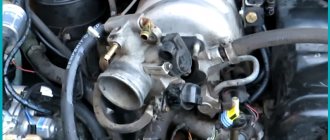
Inspecting the carburetor
We check the solenoid valve on the carburetor (if there is one). To do this, turn on the ignition, turn it off, and then turn on the contact on the valve. Clicking sounds indicate that the valve is working properly.
Start the engine, remove the vacuum tube from the distributor and touch it with your tongue. You should not feel thin air. If it is, unscrew the stopper a little.
Press down the choke handle and open the air filter. In a carburetor, the primary chamber damper must be vertical.
Pull the choke all the way, fill three cubic meters. cm of gasoline on top of the valve. It should not seep through noticeably for 5-10 seconds. Press down the choke handle, press the gas pedal and see if the damper opens smoothly or if it sticks.
Unscrew the adjusting levers on the carburetor, lubricate the O-rings with oil and tighten until the screws touch the seat in the carburetor.
Let's start adjusting
- Regulating the quality of the mixture, unscrew it by 2–3 vol.
- Unscrew the big one 1.5 turns.
- Start and warm up the engine. It will work with an extended choke, even if the idle speed is misadjusted.
- Warm up the internal combustion engine, turn off the choke. If the engine shakes or stalls, unscrew the quantity dispenser, achieving stable speed. At high speeds, tighten the screw until they decrease. We achieve a stable frequency of about 900 per minute.
- We adjust the quality by wrapping until interruptions appear, and then unscrewing until it works stable.
- The crankshaft speed will change. Using the mixture quantity screw we achieve stable speed.
- We repeat the adjustment 2-3 times with both jets.
The more you can unscrew the screw that regulates the amount of mixture supplied, the leaner it will be and the less fuel consumption will be. It will be possible to screw in more, which is responsible for the quality of the mixture - there will be less CO in the exhaust gases. But, I repeat again: this applies to idle speed, and nothing more.
Adjusting the engine idle speed on a VAZ 2106 car
Adjusting the engine idle speed should ensure the minimum possible amount of toxic substances in the exhaust gases. If the content of toxic substances exceeds the standards, operation of the VAZ 2106 is prohibited.
WARNING Perform idle adjustment with the air filter installed on a warm engine (coolant temperature 90-95 °C) with the fuel level in the float chamber and clearances in the valve drive adjusted and the ignition timing correctly set. The choke must be fully open (check this visually through the carburetor neck). Since the crankshaft speed at idle and the carbon monoxide (CO) content in the exhaust gases are adjusted together, and a gas analyzer is required to adjust the CO content, we recommend that these operations be performed at a service station.
Location of the idle speed system adjustment screws: 1 — mixture composition (quality) screw; 2 — mixture quantity screw.
NOTES The screws are located deep in the sockets of the throttle body, so screw 1 is not visible in the photo. On the new VAZ 2106 car, plastic restrictive bushings are pressed onto screws 1 and 2, allowing the screws to be turned only half a turn. This is done to prevent the factory settings from being violated. If it is not possible to adjust the CO content in the exhaust gases with the bushings, then, by unscrewing the screws, break the heads of the bushings, unscrew the screws, remove the remaining bushings from them and tighten the screws again.
1. Start the VAZ 2106 engine. By rotating the mixture quantity screw 2, set the engine crankshaft speed within 750-800 min. When tightening the screw, the rotation speed decreases; when unscrewing, it increases. 2. After this, check and, if necessary, adjust the CO content. We recommend setting the CO content to (1±0.3)%. Make adjustments using composition (quality) screw 1. When tightening the screw, the CO content decreases, and when unscrewing, it increases. According to amendment No. 1 to GOST 17.2.2.03-87, which came into force on January 1, 2000, the CO content in the exhaust gases of cars (if it is not specified by the manufacturer in the operating manual) equipped with a carburetor and without a catalytic converter in the exhaust system , at a crankshaft speed of 800 min should not exceed 3.5%. Don't reduce
the CO content is below 0.4%, since in this case, due to misfires of the working mixture in the exhaust gases, the content of unburned hydrocarbons (CH) sharply increases. When adjusting the CO content, the crankshaft rotation speed changes slightly. 3. Restore screw 2 to the original crankshaft speed of 750-800 min and check the CO content. If necessary, readjust the CO content and then the rotation speed. Press the accelerator pedal sharply and release it. The engine should increase the crankshaft speed without interruption, and should not stall after releasing the pedal. If the engine has stopped, increase the rotation speed with screw 2 to 800 min, but no more.
USEFUL ADVICE In the absence of a gas analyzer, you can adjust the idle speed with sufficient accuracy by monitoring the engine crankshaft speed using the tachometer in the instrument cluster of the VAZ 2106. Smoothly rotating screw 1 (quality) in the desired direction, set it to the position at which the idle speed maximum. Then use screw 2 (quantity) to set the frequency to 1100 min. Gradually turning in the quality screw, reduce the frequency to 800 min. If the carburetor is working properly, the CO content in the exhaust gases with this adjustment method will not exceed 2%, which is within acceptable limits.
Clock connection diagram
With the release of the “Six”, the VAZ 2106 watch did not undergo any fundamental changes. The clock connection diagram, which can be viewed here, has not changed either. The circuit diagram of the clock is tied to the ignition switch and the safety element block. At the same time, the kinematic diagram for connecting the VAZ 2106 watch is designed in such a way that the chronometer works regardless of the position of the ignition key, i.e. The "six" clock works even when the ignition is off.
If the problem is connecting the VAZ106 watch, then there is nothing complicated in this technical operation, and no difficulties are foreseen. At the same time, when solving the problem of how to connect a clock, you need to connect one wire to ground, and connect the remaining two plugs to +12 volts to the clock network and to its backlight. According to the color of the wires, which can be different, the positive wires should be the same color, usually red, and a black braided wire should be attached to ground.
When buying a VAZ 2106 watch, the price of these products is small, but due to the fact that they are morally outdated due to their low information content, car enthusiasts initially install the same chronometers from the “seven” instead of watches, and many tune this device with LED backlighting or insert such a timing device from foreign vehicle models.
Taking into account the simplicity of the design, this element of the car’s instrumentation rarely fails, so such an operation as repairing a VAZ 2106 watch needs to be resorted to quite rarely. However, in practice there are cases when watch repair is simply necessary due to its failure.
“Six” watch repair
The chronometer malfunction may be of the following nature:
- a mechanical defect in the mechanism of the “six” watch; in this case, do not carry out repairs, but immediately begin replacing the product;
- malfunction of the device lighting system;
- failure of electrical parts or their connections.
In the event of malfunctions in the electrical part of the product that can be eliminated during repair work, it is necessary to dismantle the device and replace the faulty elements.
Removal and installation of the chronometer
- We prepare the vehicle and tools for repair work;
- Disconnect the negative wire from the battery (disconnect the vehicle ground);
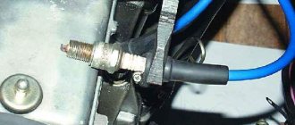
- Using a screwdriver, pry the plastic ring through the grooves on the side of the watch and pull the product out of the installation location;
- The retaining ring is removed with the product;
- When replacing the clock backlight of a VAZ 2106 car, a W3W electric lamp is used, which must be unscrewed from the installation socket and replaced;
- When removing the device, mark the wires and disconnect them from the contacts of the product;
- During installation (reinstallation), we fasten the installation ring, aligning the protrusions with the holes on the instrument panel;
- We connect the marked wires and secure them to the instrument panel.
Hours of freedom
The instrument panel of the “six” is quite informative; it contains instruments for measuring speed, engine speed, an oil pressure sensor, a coolant temperature sensor and a sensor showing the remaining amount of fuel in the fuel tank.
As for the operation of the generator device, if there is no energy regeneration, the “control” lights up. But this already becomes known after the generator fails. To prevent the creation of such a situation, it is advisable to install a device such as a VAZ 2106 voltmeter clock, which is already equipped with VAZ-2105 cars of the last 07 years of production.
For this installation you will need:
- UAZ voltmeter,
- Electrical wire 20-25 cm,
- Special input connector (“female”)
Important note: when repairing electrical devices and connecting circuits, it is necessary to de-energize the equipment by removing the negative battery cable from the connector. This is necessary to prevent short circuits and failure of the vehicle’s electronic equipment.
Algorithms for setting the clock of the VAZ 2106 voltmeter
- We remove the factory clock on the VAZ 2106 from the mounting location, disconnect the supply wiring;
- We connect the clock of the VAZ 2106 voltmeter to the positive contact of the backlight of the interior box. The contact is activated when the ignition is turned on.
- It is not possible to use the factory electrical circuit on the chronometer due to the constant activation of the contact, which can lead to battery discharge if the vehicle is stored for a long time;
- We lay the leash from the place where the chronometer is fastened to the side of the interior box to the place where the device is illuminated and connect the wires in the required way, and fasten the output end of the wire with a “female” connector;
- Remove the voltmeter fasteners;
- To securely fasten the voltmeter, we wrap it in several layers of fabric insulating tape. We install the ring - the seal from the chronometer, the backlit cartridge and connect the wiring;
- We insulate the old wire from the red “six”, because it is under constant voltage.
Tachometer VAZ 2106
The first car from the Zhiguli family equipped with a tachometer was the VAZ 2103. Neither the “kopek” nor the “two” had such a device, but they drove and drive without it to this day without any problems. Why did the designers need to install it on the panel?
Purpose of the tachometer
The tachometer is used to measure the crankshaft speed. Essentially, it is a revolution counter, showing the number of revolutions to the driver by deflecting the scale needle to a certain angle. With its help, the person sitting behind the wheel sees in what mode the car’s power unit is operating, and also whether there is any excess load on it. Based on the information received, it is easier for the driver to select the correct gear. In addition, the tachometer is indispensable when adjusting the carburetor. It is its indicators that are taken into account when adjusting the idle speed and the quality of the fuel mixture.
The tachometer is located to the left of the speedometer
More about the VAZ 2106 speedometer: https://bumper.guru/klassicheskie-modeli-vaz/elektrooborudovanie/panel-priborov/spidometr-vaz-2106.html
What tachometer is installed on the VAZ 2106
“Sixes” were equipped with the same tachometer as “threes”. It was a TX-193 model. Precision, reliability and excellent sporty design have made it a kind of standard automotive device. It is not surprising that today many car owners install these tachometers as additional devices. Moreover, they are equipped with motorcycle and even boat engines. As for the Zhiguli, the device can be installed without modifications on such VAZ models as 2103, 21032, 2121.
TX-193 is distinguished by accuracy, reliability and versatility
Table: main technical characteristics of the TX-193 tachometer
| Characteristic | Index |
| Catalog number | 2103–3815010–01 |
| Bore diameter, mm | 100 |
| Weight, g | 357 |
| Indication range, rpm | 0 – 8000 |
| Measuring range, rpm | 1000 – 8000 |
| Operating voltage, V | 12 |
TX-193 is still on sale today. The cost of a new device, depending on the manufacturer, varies between 890–1200 rubles. A used tachometer of this model will cost half as much.
Design and principle of operation of the TX-193 tachometer
The “six” tachometer consists of:
- plastic cylindrical body with glass holder;
- a scale divided into zones of safe and dangerous modes;
- backlight lamps;
- a milliammeter with an arrow attached to its shaft;
- electronic printed circuit board.
The design of the TX-193 tachometer is electromechanical. The principle of its operation is based on measuring the number of electric current pulses in the primary (low-voltage) circuit of the car’s ignition system. In the VAZ 2106 engine, for one revolution of the distributor shaft, corresponding to two rotations of the crankshaft, the contacts in the breaker close and open exactly four times. These pulses are removed by the device from the final terminal of the primary winding of the ignition coil. Passing through the parts of the electronic board, their shape is converted from sinusoidal to rectangular, having a constant amplitude. From the board, the current flows to the winding of the milliammeter, where, depending on the pulse repetition rate, it increases or decreases. The arrow of the device reacts precisely to these changes. The greater the current, the more the arrow deviates to the right and vice versa.
The design of the TX-193 is based on a milliammeter
Electrical diagram for connecting the tachometer VAZ 2106
Considering that the VAZ 2106 was produced with both carburetor and injection engines, the tachometer connection was different. Let's consider both options.
Connecting a tachometer in carburetor VAZ 2106
The electrical circuit of the speed counter of the carburetor “six” is quite simple. The device itself has three main connection wires:
- to the positive terminal of the battery through the contact group of the ignition switch (red);
- to the “ground” of the car (white wire with a black stripe);
- to terminal “K” on the ignition coil connected to the breaker (brown).
The tachometer has three main connections: to the ignition switch, to the ignition coil and to the vehicle ground.
More information about the design of the VAZ 2106 carburetor: https://bumper.guru/klassicheskie-modeli-vaz/toplivnaya-sistema/karbyurator-vaz-2106.html
There are also additional wires. They serve for:
- supplying voltage to the backlight (white);
- connections to the battery charge indicator relay (black);
- contact with the oil pressure sensor device (gray with a black stripe).
The wires can be connected either using a block or separately, depending on the year of manufacture of the device and its manufacturer.
In carburetor “sixes” with contactless ignition, the tachometer connection diagram is similar, except that the “K” terminal of the coil is connected not to the breaker, but to contact “1” of the switch.
In a contactless ignition system, the tachometer is connected not to the coil, but to the switch
Connecting a tachometer in injection VAZ 2106
In the VAZ 2106, equipped with engines with distributed injection, the connection diagram is slightly different. There is no breaker, no switch, no ignition coil. The device receives fully processed data from the electronic engine control unit (ECU). The latter, in turn, reads information about the number of crankshaft revolutions from a special sensor. Here the tachometer is connected to the power circuit through the ignition switch, the vehicle ground, the computer and the crankshaft position sensor.
In injection VAZ 2106, the tachometer, in addition to the ignition switch, has a connection to the computer and the crankshaft position sensor
How does a carburetor work in a VAZ-2106 car?
Before proceeding directly to setting up the carburetor, we will describe its structure in detail. Since about 1980, the manufacturer began installing such devices known to our compatriots as Solex and Ozone on VAZ-2106 cars, so we will focus your attention on them.
The following elements are used in the design of these carburetors:
- float chamber in which the needle valve is located. Its main task is to maintain a stable level of fuel entering the device;
- a dosing system in which the required amount of fuel is set using a special throttle valve;
- control mechanisms that regulate the position of the throttle valves and enrichment of the air-fuel mixture;
- an econostat designed to use fuel wisely, as well as an accelerator pump;
- idle system.
The carburetor works on a very simple principle. The fuel moves from the float chamber to a special compartment in which it is mixed with air.
All proportions are regulated by dampers. If the settings are made correctly, a mixture is obtained that ensures normal engine starting. Otherwise, you will encounter the following problems:
- severe overheating of the engine even at low load;
- the appearance of black smoke from the exhaust pipe;
- excessive fuel consumption;
- a significant reduction in the power of the power unit.
To fix these problems, you need to properly adjust the carburetor, which we will do below.
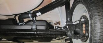
Wiring diagram VAZ 2106
The VAZ 2106 fuse box is one of the simplest devices on which the operation of the vehicle’s electrical equipment depends. For its normal functioning, the owners of the “six” need to know what equipment the fuses are responsible for and how they are replaced. During the operation of the “six”, faults often arise in the electrical circuit, which are difficult to identify if there is no electrical power. car electrical diagram. The wiring diagram is necessary for repairing lighting lamps, alarm systems, ignition switches, and other equipment. You can’t do without it in cases where you need to connect additional devices.
Electrical diagram of VAZ-2106 cars 1 - headlights; 2 — sidelights; 3 — side direction indicators; 4 - battery; 5 — battery charge indicator relay; 6 — relay for turning on low beam headlights; 7 — relay for turning on the high beam headlights; 8 — engine compartment lighting lamp; 9 — carburetor solenoid valve; 10 - starter; 11 - generator; 12 — electric motor of the engine cooling system fan; 13 — sound signal; 14 — fan motor activation sensor; 15 — spark plugs; 16 — low oil pressure indicator sensor; 17 — oil pressure indicator sensor; 18 — low brake fluid level indicator sensor; 19 — coolant temperature indicator sensor; 20 — windshield wiper electric motor; 21 — ignition coil; 22 — ignition distributor; 23 — electric motor for windshield washer; 24 — relay for turning on the fan electric motor; 25 - voltage regulator; 26 — windshield wiper relay; 27 — additional fuse block; 28 — main fuse block; 29 — reverse light switch; 30 — brake light switch; 31 — plug socket for a portable lamp; 32 — relay-interrupter for alarm and direction indicators; 33 — heater motor switch; 34 — additional resistor of the heater electric motor; 35 — heater electric motor; 36 — glove box lighting lamp; 37 — clock; 38 — cigarette lighter; 39 — alarm switch; 40 — carburetor air damper closed indicator switch; 41 — instrument lighting switch; 42 — windshield wiper and washer switch; 43 — switch for headlights and direction indicators; 44 — ignition switch; 45 — rear fog lamp switch; 46 — external lighting switch; 47 — switches for interior lighting, located in the front door pillars; 48 — switches for interior lighting, located in the rear door pillars; 49 — interior lamps; 50 — parking brake indicator switch; 51 — instrument lighting lamp; 52 — fuel level indicator with reserve indicator; 53 — coolant temperature indicator; 54 — oil pressure indicator with low pressure indicator; 55 — parking brake indicator; 56 — battery charge indicator; 57 — indicator for closing the carburetor air damper; 58 — tachometer; 59 — signaling device for turning on the side light; 60 — turn signal indicator; 61 — indicator for turning on the main beam of headlights; 62 — speedometer; 63 — indicator of insufficient brake fluid level; 64 — rear lights; 65 — license plate lights; 66 — sensor for level indicator and fuel reserve; 67 — trunk lighting lamp; 68 — rear fog lamp; 69 — sound signal switch; A - conventional numbering of plugs in the windshield wiper blocks and its relay; B - numbering of plugs in the block of relay-breaker 32 of the alarm and direction indicators; B - numbering of plugs in switch block 39 of the alarm system
Return to contents
Electrical wiring design of the “six”
The main feature of the VAZ 2106 circuit is that all the terminals of components and devices with a minus sign are directly connected to the ground of the car body. Due to its design, the wiring of the “six” has the following solution.
| Nodes | Characteristics |
| Basic emails machine chains. | They are activated via the ignition switch. |
| Electrical equipment responsible for safety. | It is connected to the battery directly through the fuse box. |
| Main components of a car. | All of them have conductive housings. |
Considering the features that el. wiring diagram of the “six”, the following point is important: replacement of any part must be carried out after the negative terminal is removed from the battery. If you touch the terminals and body of the vehicle with metal tools during repairs, a short circuit will occur. Especially for possible emergency situations in a VAZ 2106 car, regardless of the position of the key in the ignition switch, the following electrical equipment is energized:
- email horn chain;
- backlight and brake lights;
- alarm;
- cigarette lighter;
- socket.
If you service your vehicle yourself, then from time to time you are faced with the problem of failure of one or another electrical system. Email will help you figure out the problem. wiring diagram. Having a VAZ 2106 electrical diagram, you can test the circuit using a voltmeter, determine the location of the breakdown and repair the equipment.
The search for the location of the breakdown should begin with the ignition switch. This multifunctional device acts as a control mechanism for the ignition, a car security system and makes it possible to tow the car when the hazard lights are on.
Return to contents
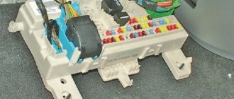
Fuse blocks: design and replacement
The main electrical equipment of the car is protected by fuse blocks. The device consists of two lines of fuses secured with two nuts to the car body. Location - under the instrument panel to the left of the steering wheel. The fuse diagram, in addition to the main and additional blocks, includes the lock drive lever on the hood of the car.
The wiring of the “six” is designed in such a way that the main fuse block ensures the safety of all electrical components. systems, and an additional one - circuits for the drive of the cooling system, direction indicators, and alarm systems. This wiring diagram ensures the safety of all connected devices and devices. If the current in any of the protected circuits exceeds the threshold value, the fuse thread will melt and the circuit will open.
VAZ 2106 owners should know that the old design of fuses has long become obsolete, since each time they are triggered they overheat, which affects the cell connection density. Lack of tight contact between the fuse and the connectors leads to their burning. Therefore, replacement of the fuse blocks is necessary. To avoid unnecessary problems with the electrical wiring, you should inspect the safety devices every six months. If the contact part burns, it is necessary to replace the fuses and clean the sockets.
Today, many VAZ 2106 owners are modernizing classic blocks, replacing them with modern blade fuses, which provide:
- tighter contact with the seat;
- when activated, instant heat removal prevents overheating.
Your six will last for many years if you provide it with constant maintenance. This is especially important for wiring a VAZ 2106 car.
expertvaz.ru
The main stages of setting up a VAZ-2106 carburetor
In order for the adjustment to be carried out in full accordance with the requirements of the car manufacturer, you will first need to carry out several preliminary procedures:
- adjust the thermal clearances of the gas distribution mechanism;
- fully open the damper through which air is supplied to the device;
- We set the correct ignition timing.
After this, the setup is carried out in several main steps:
- adjust the position of the float in the corresponding chamber. The thing is that at a high level of its installation, excessive enrichment of the mixture will be observed, which will lead to excessive fuel consumption without a significant increase in power;
- we check the patency of the needle valve holes and, if necessary, restore it by cleaning the needle;
- adjust the idle speed using the quality and quantity screws. To correctly perform this procedure, it is better to use a gas analyzer;
- we adjust the rods in order to ensure the throttle valve travel reserve.
Subtleties of idle adjustment
The most difficult of the stages listed above is the idle speed adjustment, so we will describe this procedure in more detail. It is performed as follows:
- Using the quality screw, we set the crankshaft speed at up to 900 rpm. In this case, the air damper must be completely open;
- set the maximum engine speed using the same screw;
- turn the quantitative screw. The main task is to achieve the engine speed according to the tachometer at the level of 950-1050 rpm;
- we continue tuning until the above rotation speed indicators coincide with the maximum parameters set by a high-quality screw;
- return the quality screw to the level at which the crankshaft speed was 800-900 rpm.
Using a gas analyzer, this process is performed much faster, however, as mentioned above, this device is quite expensive and is not accessible to everyone.
Correct tuning of the carburetor provides a very significant increase in the power of the car engine, and also allows you to significantly improve its dynamic characteristics. In addition, competently performed adjustment provides maximum protection against failures in the operation of the power unit both at medium and low speeds, and improves the responsiveness of the engine to pressing the gas pedal.
Adjusting the idle speed on a VAZ 2106
First you need to prepare the car. We warm up the engine to a temperature of 900 degrees. We ensure that the engine operates stably at idle speed.
Let's watch a video in which everything is shown in an accessible and understandable way:
The text instructions are as follows:
- Using the quantity screw, we achieve a crankshaft speed of 820 to 900 rpm.
- Using the quality screw, we bring the unit into stable and uniform operation. Then, by tightening the screw, we destabilize the operation of the motor and unscrew it again to restore it. Our task is thus to achieve the most stable engine operation with the leanest possible mixture.
- Using the quantity screw, we again bring the speed to the desired value.
- It is best to carry out the operation two or three times.