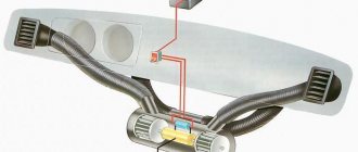
Fuel module
The task of the fuel module is to supply gasoline at the required pressure to the fuel rail. The unit consists of a fuel pump, a fuel level sensor in the tank, and a filter mesh. The pressure in the system can be influenced by both the degree of clogging of the coarse filter and the performance of the pump.
Normal pressure in the Sens fuel system is from 3 to 3.5 atm . In this case, it is necessary to take into account the degree of wear of the pump itself and the primary filter. For example, depending on the condition of the pump, the pressure may drop to a critical 2 atmospheres . A clogged filter mesh can also lead to such consequences.
With such pressure in the system, the engine is physically unable to start.
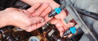
To check the condition of the fuel pump, you need to insert the key into the ignition switch and turn it to the ignition on position. At this moment, the fuel pump should start and pump fuel into the ramp. If the filter is clean and there are no problems with the pump.
The principle of operation of the fuel pump when starting the engine on a Chevrolet Lanos
Every Lanos owner should hear the sound of the fuel pump in the tank when the ignition is turned on. This sound should last 3-4 seconds.
During this time, pressure builds up in the fuel system . After this, the electronic unit turns off the pump. The pump will start working again after the crankshaft spins and impulses are sent to the electronic unit. In this case, voltage will be supplied to the fuel pump coil, which will ensure that the fuel pump turns on again.
How to check its operation
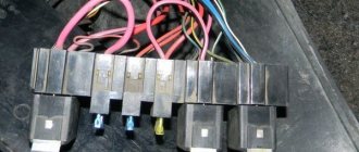
The fuse box under the hood is marked with an arrow.
When there is no such sound when you turn the ignition key, the first thing you should do is open the hood. After this, it is worth checking fuse Ef16 (15A) .
The main reasons for lack of charging
Electrical system problems are often difficult to diagnose because they can be caused by either the alternator or a faulty battery. To understand the differences, you need to know the reasons why the generator may not provide a charge. Then you need to carry out diagnostics, which will allow you to determine whether the problem really lies in the generator.
Below are the 5 most common reasons why your alternator may not be charging your battery.
- Error in the control unit. Most of the cars in use were produced no more than 20 years ago, and many models are controlled by a computer system that also controls the generator. If an error occurs in the corresponding control unit, the operation of the generator may be impaired. At the same time, it will stop charging the battery.
- Damage to the drive belt and pulley. The belt and pulley are elements that are sources of mechanical energy, which is then converted into electrical energy. The belt breaks easily due to stretching, and the pulley can be damaged during operation. In both cases, the generator will not be able to generate electrical energy.
- Blown fuse. In some cases, a separate fuse may be provided for the generator. Over time or as a result of a short circuit, it may burn out, after which the generator will become inoperable. However, not all vehicles have this type of fuse, so you must consult your owner's manual to determine if your vehicle has one. If yes, then you need to check its condition - there is a possibility that its failure is the reason for the inoperability of the generator.
- Wire fault. The electricity generated by the generator is supplied to consumers through a network of wires. It is enough to damage or disconnect one of them, and the generator will stop charging the battery.
- Alternator or battery malfunction. Generators and batteries do not last forever; their resource is limited. The battery life is 2–5 years, depending on operating conditions. Batteries last longer in cold climates and less in hot climates.
Working principle of a car fuse
The components of automotive fuses are elements such as a body and a fuse link. Chevrolet and Daewoo Lanos vehicles are equipped with flag or plug-type devices. The body of such devices is made of plastic. The fuse link is located inside the housing, which does not necessarily have to be sealed. Two contacts (legs) protrude from the body, through which the part is installed in the electrical circuit of a certain device.
The most important parameter of a fuse is the amount of current it is designed for. All devices are designed to protect electrical wiring from fire, as well as prevent failure of electrical appliances. In simple terms, a fuse protects electrical equipment from short circuits and the flow of high current. High current can lead to melting and subsequent spontaneous combustion of the wiring.
The fuse link of the element is designed for a certain amount of current, which depends on the power of the pantograph (electrical equipment). As soon as the current in the circuit exceeds the rated value for which the fuse is designed, the fuse-link burns out. As a result, the circuit opens, thereby preventing melting of the wire insulation and failure of electrical appliances.
Once a fuse has tripped, it cannot be repaired and must be replaced with a similar current rating. It should be installed in place of the failed element only after the cause of the device’s operation has been identified. If, when replacing a failed fuse, you install a device with a lower or higher current strength, this will lead to the following situations:
- If the current is below the rated current, the device will trip when electrical appliances are turned on
- If the current is higher than the rated current, the fuse will not work, which will lead to melting of the insulation, as well as failure of the electrical appliance.
The rating of the protective element is indicated on the front side of the product. Additionally, manufacturers produce devices that vary in color. The color corresponds to the current strength for which the protective device is designed. Below is a table showing the device rating depending on color.
Using a table with colors is very convenient when the fuse rating is not visible. If you don’t know what rating a protective element should have in a circuit with a particular electrical appliance, then you shouldn’t guess. You can calculate it or use the information provided below.
Re: ZAZ Sens won't start when cold.
Message from
Sergey reg16Open the control unit and check for water. gasoline enters the intake manifold through the membrane. Coolant level, how about compression? throw in another control unit that is known to be good. The crankshaft sensor also often suffers from water; it flows through the wire under the plastic of the housing. And finally, fill in another gasoline.
The block is dry, the surrounding area is also dry, the RTD is new (it was changed a month ago), the level does not go anywhere, the compression is 12/11.8/12/12 +-0.1, there is no known good ECU and nowhere to get it, the DPCV does not look bad (how to check it? ), fresh gasoline did not help.
Vadim UA
, the temperature differs by 2 degrees...
Checking the fuel pump activation circuit of a Chevrolet Lanos
If the fuel pump does not turn on when the ignition is turned on (its operation can be checked by ear), there may be a malfunction of both the fuel pump itself and its activation circuit. We begin checking the fuel pump activation circuit by assessing the integrity of fuse EF16 (15A), located in the mounting block of the engine compartment.
We replace the faulty fuse with a new one, having first checked whether the right (in the direction of travel) terminal of the fuse socket is shorted to ground. A malfunction in the fuel pump switching circuit may be caused by damage to the K9 pump relay in the mounting block. To check the relay...
...remove it from the mounting block and replace it with a known good one, type 906.3747-30. For this purpose, you can use the K7 power window relay. If the fuel pump turns on with the newly installed relay, the fuel pump relay has failed and must be replaced. If not, check the power circuit and control circuit of the fuel pump relay. To check the relay control circuit and the fuel pump power circuit, remove the relay from the mounting block.
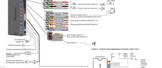
We measure the voltage between socket “30” of the mounting block and ground. The device should detect a voltage equal to the on-board network voltage. If this is not the case, the mounting block is faulty. We also measure the resistance between the “85” socket of the mounting block and ground. If the ground circuit is working properly, the device should register a resistance of less than 1 ohm. With the ignition on, measure the voltage between socket “86” of the mounting block and ground. The device should detect a voltage of about 12 V. If this does not happen, check the serviceability of the circuit between socket “86” and terminal “K54” of the ECU harness block. If the circuit is OK, the ECU is faulty. We install the relay in place and disconnect the wiring harness block from the fuel module (see “Removing and disassembling the Chevrolet Lanos fuel module”).
Elimination methods
Now that the causes and possible systems where the problem will be hidden have been found, it will be necessary to conduct computer diagnostics and find the malfunction. This will require tools, as well as knowledge of the design features of Daewoo Lanos.
It is worth immediately warning that if the owner does not know how his car works, it is recommended to contact a car service center. So, let's consider the sequence of operations that will be aimed at correcting the problem, as well as returning the power unit to its previous strength.
Fuse and relay box under the hood
It is located near the battery and is closed with a protective cover, which is held on by two side latches.
Block diagram
Description of fuses and relays Chevrolet Lanos
Circuit breakers
| EF1 | 80A Fuse circuits EF15 - EF20 and F1 - F7 |
| EF2 | 30A Ignition switch (power supply circuit for instrument cluster and fuel pump) |
| EF3 | 30A Ignition switch (starter, heater fan, power windows) |
| EF4 | 30A Electric motors of the main and additional fans |
| EF5 | 30A Electric window motors |
| EF6 | 50A Not used |
| EF7 | 30A Rear window heating element |
| EF8 | 30A Heater fan motor (4th speed) |
| D9 (diode) | Air conditioning compressor electromagnetic clutch |
| EF10 | 20A Headlight bulbs (high beam) |
| EF11 | 10A Lamp for the left headlight (low beam), motor-reducer for adjusting the direction of the light beam of the left headlight |
| EF12 | 10A Lamp for the right headlight (low beam), motor-reducer for adjusting the direction of the light beam of the right headlight |
| EF13 | 10A Brake signal/side light lamp in the left rear light (side light), instrument cluster illumination, melodic signal, side light lamp in the left headlight, headlight beam adjustment switch, fog light switch in the rear light, clock, switch hazard warning lights, ashtray lights, audio system, chevrolet lanos air conditioning switch |
| EF14 | 10A Brake/side light lamp in the right rear light (side light), side light lamp in the right headlight, license plate lights |
| EF15 | 15A Chevrolet Lanos fog lamps |
| EF16 | 15AT fuel pump |
| EF17 | 10A Horn |
| EF18 | 10A Electromagnetic clutch of the air conditioning compressor |
| EF19 | 25A Contact “30” headlight relay |
| EF20 | 20A Contact “30” side light and interior lighting relay |
Relay
| Name | |
| K1 | Sound signal |
| K2 | Headlight bulbs |
| short circuit | Air conditioning compressor electromagnetic clutch |
| K4 | Additional cooling fan motor |
| K5 | Fog lamps |
| K6 | Side light lamps in the headlights, brake signal/side light lamps in the rear lights (side light), instrument cluster illumination lamps, interior courtesy lamp |
| K7 | Power window motors |
| K8 | Main cooling fan motor |
| K9 | Fuel pump motor |
| K10 | Rear window heating element |
| K11 | Relay for the electric motors of the main and additional cooling system fans |
Lanos fuse diagram
The following diagrams in Russian, where a description of the placement of each element is indicated, are taken from factory data and are relevant for machines produced in 2006.
Fuse pinout
It is not included in standard electrical diagrams. Here you can find only individual circuit elements and the terminals of the inserts responsible for their protection.
Lanos air conditioner fuse: where is it located?
The system's inserts and relays are divided into several sections. Fuse F13 of the interior module is installed under the hood and powers the device's switching circuit. The second element f18 includes the drive clutch, and F19 is responsible for controlling the condenser switch.
If relay K3 of the engine compartment burns out, the clutch does not operate and the element should be replaced. The 2009 version and later versions use a standard four-pin relay. An article number is not needed when purchasing - the generally accepted classification of equipment is used here.
Where is the Lanos cigarette lighter fuse located?
On cars from 2007 and the restyled version after 2008, the F10 insert for the interior module is responsible.
Fuel pump fuse
The fuel pump power supply is also divided into circuits. Power elements F2 and 16 supply voltage to the motor of the part through relay K9.
This prevents sudden device failure and increases driving safety.
The price of relyushki for Daewoo Lanos starts from 50 rubles.
Turn safety
Operation is regulated by element F15 of the interior compartment. The relays are installed separately, under the dashboard. Due to the specifics of production, the easiest way to search for a relay is by the characteristic clatter of the part. Usually it is mounted under the board. When replacing, any other relay with the appropriate number of contacts will do.
Central lock fuse
Only one fuse F4 protects. Next, power is supplied to the door servos and the corresponding control keys. There is no relay in the main unit; you should look for it in the driver's door of the car.
Cooling fan fuse
The element is mounted under the hood at number 2. From here, power is supplied to the control relays K4/8 of the main and auxiliary fans. The radiator is blown efficiently, even if one of the components fails.
You can check the main fan switch by connecting the device directly from the battery.
Starter fuse
The EF3 starter element is located in the engine compartment. It supplies voltage to the additional relay. Next, the chain goes to the retractor and the motor starts.
The circuit relay is mounted under the hood on the left fender of the car.
Wiper fuse
Operation adjustment is looped through insert F18. From here, voltage is supplied to the control unit and relay No. 3, which is responsible for the intermittent operation of the device.
You can see what the compressor switch looks like in the photo.
Power window fuse
The stability of the operation of window lifting devices in the car is controlled by the fifth element of the engine block and the K7 switch. These inserts begin checking the line in the event of a module failure.
Brake lights
The feet have a separate power supply system. The wiring is duplicated and protected by fuses EF13 and 14. This design ensures that the luminaires continue to operate in the event of damage to one part of the circuit.
Signaling
It is protected by element 17 and relay K3 of the on-board circuit.
The car's alarm system is powered through fuse 13 of the engine compartment module and element No. 3 of the cabin unit. From here the power goes to K4.
Dimension fuse
Separated along the sides. Circuit parts No. 13 and 14 are responsible for the lamps on the right and left sides of the machine. Box 20 connects the circuits together and makes them work synchronously.
The blinking mode is provided by relay switch K6. If the turn is constantly on or flashes too quickly, this is the part that needs to be replaced.
Low beam
The lighting of the left and right sides is provided by fusible elements 11 and 12 of the engine compartment installation. The relays are located there, near the headlights.
High beam
The high beam lighting is powered by only one EF10 fuse. There is no need to split the diagram into several parts. The system is auxiliary. The only relay is mounted in the same way near the headlight unit.
Radio tape recorder
Voltage is supplied directly from the battery through fuse F6. If the installation does not work after turning on the ignition, element F9 is responsible for this.
Headlights corrector
Occurs through circuit elements No. 14 and 2 of the engine compartment and cabin units, respectively. There are no relays here. Their work is performed by a gear motor.
Fuse diode
Two diodes are installed on the machine. D1 is responsible for activating the air conditioning clutch. The second alarm is activated when the door is opened.
Generator
The circuit is excited through insert F14 of the interior unit. The voltage regulator relay is located separately and is mounted on the inside of the car fender.
Accumulator charging
The insert is installed near the power source. The device is controlled through the vehicle's electronic control unit.
Interior lighting
Power fuse EF 20 works in tandem with relay K6, which ensures stable operation of the interior and interior lighting of the car. The light bulb is protected by insert No. 1.
ECU fuse
The interior panel contains elements F5 and 17. The parts supply voltage to the computer from the battery and the ignition switch.
Instrument lighting
This is done through a single safety element with interior lighting.
Trunk light
The cargo compartment has only one lighting fixture. The power circuit is looped through insert F1.
Stove lighting
The lighting is connected via fuse F20.
Fog light fuse
The car is equipped with two pairs of foglights - front and rear. At the same time, the elements are quite energy-intensive. The stern fog switches pass through insert No. 13 of the engine compartment. The lamps themselves are powered from part number 15. The power cores are closed from the K5 relay.
Wiper
The electric motor of the windshield washer reservoir is protected by element F18. He is responsible for the purifier drive. The device's switch is located separately from the rest to facilitate maintenance and free access.
Ignition
The system is powered by two fuses at once. Elements EF 1 and 2 supply voltage to the main systems. The main relay and coil wiring are powered by element F15.
Reverse
When reverse gear is engaged, the corresponding lamp on the rear of the machine lights up. The standard F12 element completely covers the requirements of the circuit and ensures its stable operation.
Heated rear window
The tenn's power wires pass through the EF7 fuse. The circuits are turned on by switch K10, and the device control system is powered via F19.
Speedometer
The vehicle speed measurement system is protected by insert F14. The element is responsible for the sensor installed on the gearbox.
Windshield washer
Information about the windshield washer is listed above.
Horn fuse
The standard Lanos horn is controlled by the EF17 insert. Next, the device circuit passes through relay K1.
Injectors
The fuel injectors of the injector are controlled through a standard F14 fusible element mounted under the board.
Fuel level fuse
The fuel level in the gas tank is controlled by a special float sensor. The sensors are under full control of the ECU. The fuse should be found in the circuit of the electronic engine control unit.
Dashboard
The control and power circuit for the board and all devices is looped through the EF2 insert. The part is responsible not only for the specified part of the wiring, but also for other departments of the machine.
Brake fuse
The signal lamp circuits are completely similar to the rear part of the side lights. Therefore, only fuses are responsible.
Number plate illumination
Lighting a state sign does not require much energy. Weak lamps operate from an EF14 part and do not exert a significant load on it.
Driver's door alarm
It is fed through a diode element located on the dashboard.
Airbag
The firing mechanism of the device is powered by fuse F13. To increase safety, the part serves only one system.
Heater relay
Separate switches are responsible for the operation of the mechanism at different speeds. Insert No. 2 is responsible for the operation of the device at speed 4.
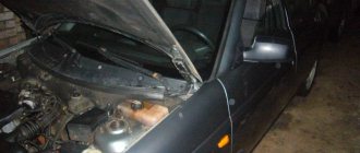
Reviving a “dead man” - is he dead?
The first sign of trouble that I noticed was the fuel pump not working. It was him who I rushed to revive first, which turned out to be not quite the right decision. If your car (or any other equipment) breaks down, carefully examine the problem from all sides: maybe there are some other signs of breakdown , because the car is a rather complex system of units (which, by the way, has its own built-in diagnostics). If I had directly connected the wire from the battery to the fuel pump connector (that is, supplied it with 12 volts, eliminating all intermediaries in the electrical circuit), I would definitely have been convinced that the pump is alive. But... the engine still wouldn’t start! Then, I would check to see if there was a spark at the spark plugs, and I would be very sad because there was none. After reading the forums, you can be horrified at how much time and money some people with the same problem spent solving it, changing one car service center for another.
What can you do if the Chevrolet Lanos does not start?
If you don’t have time to repair your car at the moment, you should relax and do other things. Determining a malfunction is a long and painstaking task.
| The starter does not turn | If it does not spin, you need to check the electrical ignition circuit. |
| No battery charging | The entire electrical system is not working. You need to replace the old battery or try cleaning the terminals with fine-grit sandpaper. The battery may simply be discharged. The way out of this situation is to try to “light” it from another car |
| The starter turns, but the car does not start. | The battery is not to blame at all here. The problem may be with the fuel system or ignition. The 2nd option is most likely, since it is the ignition that breaks down more often than others. You need to remove the distributor cap and make sure that there is no moisture through which the spark gets to another place. Using a tester, check for damage to the coil. |
If these options do not help, then the car will have to be taken to a repair shop. The main reasons why the Chevrolet Lanos does not start are the violation of three components: air supply, fuel and the occurrence of a spark. Qualified specialists will certainly help in identifying the malfunction.
Chevrolet Lanos electrical circuit
If it does not turn on, we check the power and control circuits of the electrical device. In the absence of a spare working relay, a similar method above to check the serviceability of the device is to install a jumper piece of wire between contacts 30 and 87, a paper clip, which will close them when the ignition is on.
When the ignition is turned on, it should be equal to 12 V. It is equal to the voltage of the on-board network. Its absence indicates a break in the wires between the contacts and ground.
Otherwise, you need to connect the probe between pin 85 of the relay harness block and the positive terminal of the battery.
If the probe lamp does not light up when the ignition is turned on, this indicates a malfunction of the controller or a broken wire.
Chevrolet car repair manuals and tips
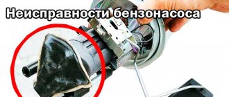
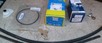
I've been wanting to replace the strainer in the fuel pump for a long time. Once I tried to open it (as I had a problem with the exhaust, there was an entry in the BZ) but it didn’t work. So the day came when I managed to open the pump and change the filter. The mesh cost 100 rubles.
Two hooks from the electrode are visible here
First, we open the top cover of the flask; it doesn’t give much of a view, but we try to open nothing. We insert one hook into the inside of the flask, we hook this hook to something, and slowly pull with force, as soon as it moves a little we change the position, when we walk around in a circle, the inner part rises a little; a second hook will be needed in order to reach the inner part of the flask without distortions. You also need to disconnect the wire connector, otherwise it won’t allow you to disassemble it completely. And when everything works out, you can rejoice, since this is the most difficult stage when replacing the mesh in the fuel pump.
Old and new mesh
I also removed the pump motor itself from its housing.
Replacement
We started the article with unexpected malfunctions of electrical appliances. Once you have an idea of what the Chevrolet Lanos fuse box looks like and what its elements are responsible for, you can begin troubleshooting. The most common failure is the cigarette lighter, so let's look at the replacement process using it as an example.
First of all, you need to make sure that the cigarette lighter is really not working. There may be several reasons why it stopped performing its direct duties or charging your gadgets:
- blown fuse;
- clogged contact;
- inconsistent charger contact due to its configuration;
- problems with wiring or contacts.
The last case is very rare and least likely. We make sure that the nest is not filled with debris, dust, ash or tobacco. If so, clean the nest. Then check if your gadget's charger fits well into the socket. Perhaps this will be the problem and will be solved by purchasing a new charger. So, if all of the above problems do not affect you, then you need to replace the fuse. It is located in the indoor unit (read above for how to get to it) and is marked F10. Using tweezers, remove the old PP, make sure that it is really burnt (black, charred, melted) and insert a new one of the same rated current (15 A) in its place.
Also, Chevrolet Lanos car owners are faced with the fact that the car will not start. This problem can often be solved by replacing the fuel pump fuse. Watch the replacement video:
Replacing fuses
Despite the fact that manufacturers have tried to make the design of the car quite simple and reliable, situations still arise when some kind of breakdown occurs in one of the fuse blocks. For example, problems often arise with the operation of the cigarette lighter, lighting and heating. There may be a malfunction in the fuel pump. Most drivers prefer to immediately go to a service station, but you can fix the breakdown yourself.
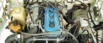
Ignition module
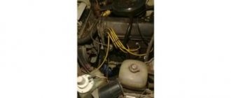
The ignition module's job is to supply voltage to the spark plugs. Over time, it may cease to perform its functions, which affects both engine starting and its operation in general.
First of all, you need to check for the presence of a spark. To do this, you need to unscrew any spark plug and place it on the ground of the car. When the engine is cranked by the starter, a spark should jump between the spark plug electrodes.
If there is no spark, you need to check the module connector. In addition, you need to check the fifth fuse from the right, its rating is 15 Amps .
There may be a problem with the contacts in the module itself. The wires in the module are made of aluminum and are not always properly soldered. Therefore, the problem with starting the engine may be intermittent. Theoretically, you can disassemble the module and solder the contacts, but this will not guarantee the functionality of the module.
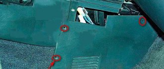
Fuse box in the car interior on the left under the trim
The interior fuse box of Lanos, Sens and Chance is responsible for protecting various electrical equipment. There are 20 fuses located on this block in the passenger compartment. Let's look at their purpose in detail.
The table below provides not only a description of the purpose of each element, but also the maximum current value. When searching for or replacing cabin fuses on a Lanos, you must rely on the data from the table.
Fuse F2 is responsible for turning off the rear PTF lamps. It also protects the power supply circuit for the headlight range control and the door open alarm. F5 - protects the power supply circuit of the vehicle's ECU. The power cable comes directly from the battery. Fuse F8 on the block is responsible for supplying power to the light alarm on the driver's door. Element F13 is responsible for the proper operation of the airbags. F15 - supply voltage to the coil or ignition module. F20 - battery for the electric heater motor for speeds 1-3.