How to replace the front crankshaft seal on a VAZ 2110-VAZ 2112?
The note!
This article covers the process of replacing the oil seal on 16 valve engines only, if you have 8 10 valves, then in that case, go to the article entitled "Replacing a Crankshaft Seal on 9s" in it, with an example of an 8 cylinder engine, everything is described!
Conclusion:
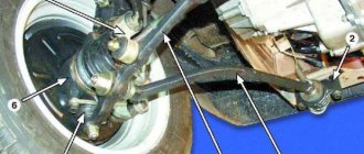
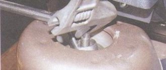
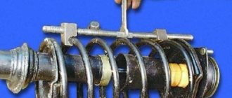
To remove the oil seal, first remove the timing belt from all the upper pulleys and rollers (as explained in the article on replacing the timing belt on a car, we already mentioned the link to this article at the very beginning of the article, scroll up), then the alternator belt will be removed, you need to remove the crankshaft pulley (How to remove the belt, described in the article: “Replacing the alternator belt on a VAZ”), after completing the operations, proceed to removing the large and small crankshaft mechanism, both gears are fixed with one bolt (it holds them in the center ), which is there (see photo 1), but to get to it, the jack must lift the right side (when you look at the car, see), remove the wheel (see article: Correct replacement of wheels on cars) and, if necessary, remove the wheelbarrow , if the suspension does not interfere, then without removing it, turn the pulley bolt and first of all, remove the large pulley from the crankshaft, install a washer on it without losing it, remove it from the large crankshaft pulley (see picture). photo 2), follow the belt with a small release of the pulley (see photo 3), and at the end remove the small pulley from the shaft, that's all, you can assume that you have hit the packing, but there is one caveat, there is a key (see
photo 4), when this is done, you can remove the oil pump cover seal using thin screwdrivers, when you remove it, note that it is on the side, Install the new packing in the same way
Any part of a modern car, no matter how high-quality and reliable it is, has its own working life, upon reaching which it must be replaced, which allows for the most comfortable and safe operation of the entire propulsion system. Crankshaft oil seals are no exception; they should be diagnosed and replaced approximately every three years. Today we will talk about how to replace the front crankshaft oil seal at home.
When may repair dimensions of crankshafts be required?
First of all, let's look at the different types of defects that occur, as well as the reasons for their occurrence. If the geometry of the seats for the support bearings of the block is broken, rapid wear of the journals should be expected. In other words, if this process is observed, the reason is most likely exactly the same as indicated above, or in the poor quality of the material of the shaft itself. Due to poor-quality oil or its irregular replacement, scuffs may appear on the necks; a clogged oil filter, or, which is even worse, low pressure in the system, can also be the source of this trouble.
Toyota pistons markings
The pistons on Toyota engines also have their own designations and sizes. For example, on the popular Land Cruiser, the pistons are designated by the English letters A, B and C, as well as numbers from 1 to 3. Accordingly, the letters indicate the size of the hole for the piston pin, and the numbers indicate the size of the piston diameter in the “skirt” area. The repair piston has +0.5 mm compared to the standard diameter. That is, only the letter designations change for repair shops.
Please note that when purchasing a used piston, it is necessary to measure the thermal gap between the piston skirt and the cylinder wall. It should be within 0.04...0.06 mm
Otherwise, it is necessary to carry out additional diagnostics of the engine and, if necessary, carry out repairs.
Marking of inserts for VAZ 21083
1 - connecting rod bolt nut 2 - connecting rod bearings 3 - connecting rod 4 - piston pin 5 - outer compression ring groove 6 - lower compression ring groove 7 - oil scraper ring groove 8 - piston 9 - connecting rod bolt 10 - connecting rod cap
For the convenience of selecting pistons for cylinders, cylinders and pistons, depending on the diameter, are divided into five size groups: A, B, C, D, E.
Pistons of nominal sizes of three classes are supplied as spare parts: A, C, E and two repair sizes. The first repair value is increased by 0.4 mm, the second – by 0.8 mm. By weight, pistons are divided into three groups: normal, increased by 5 g and decreased by 5 g. Pistons of a single group must be installed on the engine. For repair size pistons, repair size rings increased by 0.4 mm and 0.8 mm are supplied as spare parts. The number “40” is stamped on the rings of the first repair size, and “80” on the second.
Nominal sizes of cylinders and pistons Size group Model of the VAZ-2108 engine Model of the VAZ-21083 engine
Cylinder diameter, mm Piston diameter, mm Cylinder diameter, mm Piston diameter, mm
A 76.00-76.01 75.965-75.975 82.00-82.01 81.965-81.975
B 76.01-76.02 75.975-75.985 82.01-82.02 81.975-81.985
C 76.02-76.03 75.985-75.995 82.02-82.03 81.985-81.995
D 76.03-76.04 75.995-76.005 82.03-82.04 81.995-82.005
E 76.04-76.05 76.005-76.015 82.04-82.05 82.005-82.015 To select pistons for cylinders, calculate the gap between them. The gap is defined as the excess between the measured diameters of the piston and cylinder. The nominal gap is 0.025-0.045 mm, the maximum permissible is 0.15 mm. If the gap does not exaggerate 0.15 mm, pistons can be selected from subsequent classes to keep the gap as close to nominal as possible. If the gap exceeds 0.15 mm, bore the cylinders to the next repair size and install pistons of the corresponding repair size.
Note 1 Gap between rings and piston grooves, mm
Nominal: upper compression ring 0.04-0.075 lower compression ring 0.03-0.065 oil scraper ring 0.02-0.055 Maximum permissible gap for all rings 0.15, Note 2 Gap in piston ring locks, mm:
Maximum permissible 1.0 Piston pins are divided by diameter into three classes (1st, 2nd, 3rd) every 0.004 mm. The discharge of the finger is marked on its end with paint.
Size classes of piston pins and pistons Type Pin diameter, mm Hole diameter in piston, mm Piston pin marking
1 21,970-21,974 21,982-21,986 Blue 1
2 21,974-21,978 21,986-21,990 Young 2
3 21,978-21,982 21,990-21,994 Red 3
The piston is installed on the connecting rod so that the arrow on the bottom of the piston is directed in the opposite direction from the part number cast on the connecting rod. If there is an opening on the lower head of the connecting rod for oil to escape, the arrow on the piston must be directed towards this opening.
Procedure 1. We recommend removing the piston rings with a special puller. If it is not there, carefully push the ring lock apart and remove the ring from the piston. Remove the remaining rings in the same way. 2. Using a special mandrel, press the pin out of the connecting rod. 3. Examine the pistons. If they have scuff marks, burnout effects, or deep scratches, replace the pistons.
4. To determine the gap, check the cylinder diameter (see subsection 11.8.. and the piston diameter, which is measured with a micrometer in a plane perpendicular to the piston pin axis, at a distance of 51.5 mm from the piston bottom. 5. Check the gap between the rings and grooves with a feeler gauge piston in several places around the perimeter. If the gap exceeds the maximum permissible (see note 1), replace the pistons with rings. 6. Insert the piston ring into a special mandrel and check the gap in the lock. Instead of the mandrel, you can insert the ring into the cylinder and push it with the piston, so that the ring fits without distortion. If the gap exceeds the maximum permissible, replace the ring (see note 2). If the gap is less than 0.25 mm, carefully file the ends of the ring with a needle file.
7. Measure the fit of the piston pin in the piston. To do this, lubricate the piston pin with engine oil and insert it into the piston. The finger must enter the piston freely from pressure from the large finger of the hand. 8. Turn the piston over so that the pin stands vertically, but it does not have to fall out of the piston under the influence of its own weight. If the pin falls out of the piston, use the next class of pin. If the third class pin falls out of the piston, replace the piston and pin.
9. Examine the connecting rod bearings. If they have cracks, burrs, or chipping, replace the liners. 10. Examine the connecting rods with caps. Replace bent connecting rods. 11. Place piston pin 2 onto shaft 1 of the device for installing the piston pin with spacer ring 5 put on it. Next, put on guide sleeve 3 and secure it with screw 4 without tightening the screw. Dimensions of the spacer ring: outer diameter 22 mm, inner diameter – 15 mm, thickness – 4 mm. 12. Heat the upper head of the connecting rod to 240 ° C in the oven for 15 minutes. Clamp the connecting rod in a vice, place the piston on it (see note) so that the holes for the pin match, and insert the tool with the pin into the holes of the piston and connecting rod until the limit is reached. For correct installation of the pin, the piston must be pressed with the boss against the upper head of the connecting rod in the direction of pressing.
Is it possible to tune the Priora 126 engine?
Even with a strong desire, the 126 engine will not be able to reach a speed of 100 km/h in a few seconds. Without tuning the Lada Priora engine, overtaking prestigious brands will also not be possible.
According to many motorists, it is necessary to install a turbocharger from the very beginning. In this case, the engine power will increase by no more than 15 - 20%. Special filter elements are additionally installed here to clean the cold air as it enters the engine.
The main improvements to the 21126 motor are:
- cylinder boring;
- increase in piston stroke.
With the help of these modifications, it is possible to most effectively boost the 126 engine, the power of which increases by 50 horsepower. The main purpose of boring is to increase the volume of the cylinders. The process comes down to primitive actions:
- cylinder walls are reduced in thickness;
- more gasoline is burned in the resulting volume;
- engine performance increases;
- power increases.
When choosing a future car, we definitely pay attention to what kind of power unit (heart) it has. Not only the dynamics depend on the motor, but also how much money is required for its maintenance
Do you know which modern VAZ engine to choose?
When repair dimensions of crankshafts are required
The transition point from the main or connecting rod journal to the cheek experiences the greatest loads in the crankshaft structure, and therefore wear in this place is the greatest. As the motor operates, scuffs and cracks appear on the journals, which lead to a violation of the geometry of the shaft and must be eliminated as soon as possible. They can be removed by sanding. In order for the engine to operate in a balanced manner and without unnecessary vibration, the new dimensions of the crankshaft main and connecting rod journals must be precisely adjusted to the shaft and to each other. This is done using special inserts. For the convenience of auto mechanics, the diameters of the necks and the thickness of the liners were standardized for each car model.
Therefore, repair dimensions are required every time the crankshaft is ground. They are determined depending on the shaft processing method. During production, each shaft goes through several stages of hardening, increasing the strength and wear resistance of its surface. Most often, heat treatment is used, but in some cases, to enhance strength, the effects of high and low temperatures are combined with chemical treatment (high-frequency hardening, nitriding, hardening of the surface layer). As a result, a sufficient depth of the hardened layer is achieved so that the shaft journals can be ground 4–6 times without losing the working qualities of the shaft.
Crankshaft sample Crankshaft design:
- The main journal is the supporting part of the shaft. It is located in the engine crankcase and rests on the main bearing.
- The connecting rod journal connects the shaft to the connecting rods and at the same time ensures the supply of lubricant to them through special channels.
- Cheeks are parts connecting the main and connecting rod journals.
- The front output portion of the shaft, or toe, is where the timing gear or power take-off pulley is mounted.
- The rear output shaft or shank is where the flywheel or power take-off gear is mounted.
- Counterweights are structurally a continuation of the cheeks and remove part of the load from the main bearings.
Be sure to read: Repair of the MTZ 80 front axle, its structure and diagram
Dimensions of crankshaft journals 2108
After disassembling the engine, thoroughly clean, rinse and dry all parts.
1. Clean the piston head from carbon deposits. If the piston has burrs, burn marks, deep scratches, or cracks, replace the piston. Clean the grooves for the piston rings. It is convenient to do this with a piece of an old piston ring.
2. Clean the oil drain holes with a suitable piece of wire.
3. Check the clearances between the rings and grooves on the piston. Nominal piston ring clearance, mm: upper compression ring 1 - 0.04-0.075; lower compression ring 2 - 0.03-0.065; oil scraper ring 3 - 0.02-0.055. The maximum permissible gap for all piston rings is 0.15 mm.
4. The most accurate way to determine piston ring clearances is by measuring the rings and grooves on the piston. To do this, measure the thickness of the piston ring with a micrometer in several places around the circumference, then... 5. ...using a set of feeler gauges, also measure the width of the grooves in several places around the circumference. Calculate the average clearance values (the difference between the thickness of the piston ring and the width of the groove). If at least one of the gaps exceeds the maximum permissible, replace the piston with rings.
6. Measure the gaps in the piston ring locks by inserting the piston ring into a special mandrel. If there is no mandrel, insert the piston ring into the cylinder (in which the piston ring worked), use the piston as a mandrel to push the piston ring into the cylinder so that the piston ring is installed evenly in the cylinder, without distortions and... 7. ...measure the gap in the piston ring lock with a feeler gauge. The nominal piston ring clearance should be 0.25-0.45 mm, the maximum permissible (due to wear) is 1.0 mm. If the gap exceeds the maximum permissible, replace the piston ring.
8. If the gap is less than 0.25 mm, carefully grind off the ends of the piston ring with a file.
9. Check the clearances between the pistons and cylinders. The clearance between pistons and cylinders is defined as the difference between the measured diameters of the piston and cylinder. The nominal gap between the pistons and cylinders is 0.025-0.045 mm, the maximum permissible is 0.15 mm. If the gap between the pistons and cylinders does not exceed 0.15 mm, you can select pistons from subsequent classes so that the gap between the pistons and cylinders is as close as possible to the nominal one. If the gap between the pistons and cylinders exceeds 0.15 mm, bore the cylinders to the next repair size and install pistons of the corresponding repair size. Measure the diameter of the piston at a distance of 55 mm from its bottom in a plane perpendicular to the piston pin.
Rice. 4.9. Cylinder clearance measurement locations
10. Then measure the diameters of the cylinder in two perpendicular planes (see Fig. 4.9.) (along B and across A of the cylinder block) and in four zones (1, 2, 3 and 4). For this you need a special device - a bore gauge. 11. When replacing parts of the connecting rod and piston group, it is necessary to select pistons to cylinders by class and one group by weight, as well as piston pins to pistons by class and connecting rods by weight. To select pistons for cylinders, calculate the gap between them. For the convenience of selecting pistons for cylinders, cylinders and pistons, depending on their diameters, are divided into five classes: A, B, C, D, E (Table 4.1). Spare parts include pistons of nominal sizes of three classes A, C, E and two repair sizes. The first repair is increased by 0.4 mm, the second - by 0.8 mm. By weight, the pistons are divided into three groups: normal, increased by 5 g and decreased by 5 g. Pistons of the same group must be installed on the engine of VAZ 2108, VAZ 2109, VAZ 21099 cars. For repair size pistons, spare parts include repair size rings increased by 0.4 mm and 0.8 mm. The number “40” is stamped on the rings of the first repair size, and “80” on the rings of the second repair size.
Table 4.1 Nominal dimensions of cylinders and pistons Class Diameter, mm piston cylinder A 82.00-82.01 82.00-82.01 B 82.01-82.02 82.01-82.02 C 82.02-82, 03 82.02-82.03 D 82.03-82.04 82.03-82.04 E 82.04-82.05 82.04-82.05
12. On the cylinder block, a group of cylinders is knocked out on the lower plane of the block (the mating plane for the oil sump) opposite each cylinder. 13. The following data is stamped on the bottom of the piston: 1 - piston class based on the hole for the piston pin; 2 - piston diameter class; 3 - arrow showing the direction of installation of the piston; 4 - repair size (1st repair - triangle, 2nd repair - square); 5 - weight group (normal “G”, increased by 5 g “+”, decreased by 5 g “-”).
14. Replace piston pins with cracks. The piston pin should easily enter the piston using the force of the thumb. Insert the piston pin into the piston. If play is felt when rocking the piston pin, replace the piston. When replacing a piston, select a piston pin according to its class
Table 4.2 Classes of piston pins, pistons and connecting rods Size group Engine model VAZ 2108 Cylinder diameter, mm Piston diameter, mm A 76.00-76.01 75.965-75.975 B 76.01-76.02 75.975-75.985 C 76.02- 76.03 75.985-75.995 D 76.03-76.04 75.995-75.005 E 76.04-76.05 75.005-75.015
Size group Engine model VAZ 21083 Cylinder diameter, mm Piston diameter, mm A 82.00-82.01 81.965-81.975 B 82.01-82.02 81.975-81.985 C 82.02-82.03 81.985-81.995 D 82, 03-82.04 81.995-82.005 E 82.04-82.05 82.005-82.015
(Table 4.2). The piston pins are divided by diameter into three classes (1-, 2-, 3rd) every 0.004 mm. The class of the piston pin is marked on its end with paint. The piston pin class is stamped on the piston bottom, the connecting rod pin class is stamped on the connecting rod cap.
15. Replace broken piston rings and oil ring expander.
16. Replace broken or cracked circlips that retain the piston pin. The ends of the retaining rings must be in the same plane. Replace bent rings.
17. Replace bent connecting rods. Replace the connecting rod if there are burrs and deep scratches in the bushing 1 of the upper head. Replace the connecting rod if, upon disassembling the engine, it is discovered that the connecting rod bearings have rotated in the connecting rod. WARNING The connecting rods are processed together with the caps, so they cannot be disassembled.
18. Insert the piston pin into the upper end of the connecting rod. If play is felt when rocking the piston pin, replace the connecting rod. Connecting rods assembled with covers are divided into classes based on the weight of the upper and lower heads (Table 4.3).
Table 4.3 Connecting rod class based on the mass of the upper and lower heads Weight of the connecting rod heads, g Marking upper lower with paint letter 184+2 489±3 F Red 495+3 L Green 501±3 B 188+2 489+3 X 495±3 M 501+ 3 V 192+2 489±3 C 495±3 N 501+3 G Blue
19. In the engine of VAZ 2108, VAZ 2109, VAZ 21099 cars, connecting rods of the same class must be installed. The connecting rod is marked on the connecting rod cover: 1 - connecting rod class by weight (letter or paint), 2 - connecting rod class by piston pin.
20. If there are deep scratches, scratches, nicks on the surfaces on which the oil seals operate, the crankshaft must be replaced.
VAZ pistons marking
According to statistics, owners or engine repair technicians of VAZ cars are most often interested in the marking of repair pistons. Below we provide information on various pistons.
VAZ 2110
For example, let's take the engine of a VAZ-2110 car. Most often, this model uses pistons marked 1004015. The product is produced directly at AvtoVAZ OJSC. Brief technical information:
- nominal piston diameter - 82.0 mm;
- piston diameter after first repair - 82.4 mm;
- piston diameter after the second repair - 82.8 mm;
- piston height - 65.9;
- compression height - 37.9 mm;
- The recommended clearance in the cylinder is 0.025...0.045 mm.
Additional information can be printed directly on the piston body. For example:
- “21” and “10” in the area of the hole for the finger - designation of the product model (other options - “213” indicates the VAZ 21213 engine, and for example, “23” - VAZ 2123);
- “VAZ” on the inside of the skirt is the manufacturer’s designation;
- letters and numbers on the inside of the skirt are a specific designation of foundry equipment (you can decipher it using the manufacturer’s documentation, but in most cases this information is useless);
- “AL34” on the inner side of the skirt is the designation of the cast alloy.
The main marking symbols applied to the piston crown:
- The arrow is an orientation marker indicating the direction towards the camshaft drive. On the so-called “classic” VAZ models, sometimes instead of an arrow you can see the letter “P”, which means “in front”. Likewise, the edge where the letter is depicted should be directed towards the direction of movement of the car.
- One of the following symbols is A, B, C, D, E. These are diameter class markers that show the deviation in the outside diameter value. Below is a table with specific values.
- Piston mass group markers. “G” is normal weight, “+” is weight increased by 5 grams, “-” is weight decreased by 5 grams.
- One of the numbers is 1, 2, 3. This is a piston pin hole class marker that determines the deviation in the diameter of the piston pin hole. In addition to this, there is a color designation for this parameter. So, the paint is applied to the inside of the bottom. Blue color - 1st grade, green - 2nd grade, red - 3rd grade. The following provides additional information.
For VAZ repair pistons there are also two separate designations:
- triangle - first repair (diameter increased by 0.4 mm from the nominal size);
- square - second repair (diameter increased by 0.8 mm from the nominal size).
Please note that for different brands of cars (including for different engines), the difference between repair pistons should be found in the reference information
VAZ 21083
Another popular VAZ piston is 21083-1004015. It is also produced at OJSC AvtoVAZ. Its technical dimensions and parameters:
- nominal diameter - 82 mm;
- diameter after first repair - 82.4 mm;
- diameter after the second repair - 82.8 mm;
- piston pin diameter - 22 mm.
It has similar designations as VAZ 2110-1004015. Let us dwell in a little more detail on the class of the piston in terms of outer diameter and the class of the hole for the piston pin. The relevant information is summarized in tables.
| Piston class by outer diameter | A | B | C | D | E |
| Piston diameter 82.0 (mm) | 81,965-81,975 | 81,975-81,985 | 81,985-81,995 | 81,995-82,005 | 82,005-82,015 |
| Piston diameter 82.4 (mm) | 82,365-82,375 | 82,375-82,385 | 82,385-82,395 | 82,395-82,405 | 82,405-82,415 |
| Piston diameter 82.8 (mm) | 82,765-82,775 | 82,775-82,785 | 82,785-82,795 | 82,795-82,805 | 82,805-82,815 |
It is interesting that the VAZ 11194 and VAZ 21126 piston models are produced only in three classes - A, B and C. In this case, the step size corresponds to 0.01 mm.
Correspondence table between piston models and engine models (brand) of VAZ cars.
| VAZ engine model | Piston model | |||||||||||
| 2101 | 21011 | 2105 | 21213 | 2123 | 2108 | 21083 | 2110 | 2112 | 21124 | 21126 | 21128 | 11194 |
| 2101 | ||||||||||||
| 21011 | ||||||||||||
| 2103 | ||||||||||||
| 2104 | ||||||||||||
| 2105 | ||||||||||||
| 2106 | ||||||||||||
| 21073 | ||||||||||||
| 2121 | ||||||||||||
| 21213 | ||||||||||||
| 21214 | ||||||||||||
| 2123 | ||||||||||||
| 2130 | ||||||||||||
| 2108 | ||||||||||||
| 21081 | ||||||||||||
| 21083 | ||||||||||||
| 2110 | ||||||||||||
| 2111 | ||||||||||||
| 21114 | ||||||||||||
| 11183 | ||||||||||||
| 2112 | ||||||||||||
| 21124 | ||||||||||||
| 21126 | ||||||||||||
| 21128 | ||||||||||||
| 11194 |
Piston pin holes:
| Piston pin hole class | 1 | 2 | 3 |
| Piston pin hole diameter(mm) | 21,982-21,986 | 21,986-21,990 | 21,990-21,994 |
Connecting rod and piston group [edit]
Piston[edit]
The piston is cast aluminum. According to the outer diameter, the pistons are divided into five classes (A, B, C, D, E) every 0.01 mm. The outer surface of the piston has a complex shape. Therefore, it is necessary to measure the piston diameter only in a plane perpendicular to the piston pin, at a distance of 51.5 mm from the piston bottom. Based on the diameter of the hole for the piston pin, pistons are divided into three classes (1, 2, 3) every 0.004 mm. The classes of piston diameters and piston pin holes are stamped on the piston crown. By weight, pistons are sorted into three groups: normal, increased by 5 g and decreased by 5 g. These groups correspond to markings on the bottom of the piston: “G”, “+” and “-“. All pistons on the engine must be of the same mass group. Repair size pistons are manufactured with an outer diameter increased by 0.4 and 0.8 mm. An increase of 0.4 mm corresponds to a marking in the form of a triangle, and an increase of 0.8 mm corresponds to a marking in the form of a square. The arrow on the piston crown shows how to properly orient the piston when installing it into the cylinder. It should be directed towards the camshaft drive.
Piston pin[edit]
The piston pin is made of tubular steel, pressed into the upper head of the connecting rod and rotates freely in the piston bosses. According to the outer diameter, the fingers are divided into three classes every 0.004 mm. The class is marked with paint on the end of the finger: a blue mark is the first class, a green mark is the second class, and a red mark is the third class.
Technical characteristics of VAZ 2106
Performance characteristics of the VAZ 2106 six Maximum speed: 150 km/h Acceleration time to 100 km/h: 17.5 s Fuel consumption per 100 km in the city: 10.1 l Gas tank volume: 39 l Curb vehicle weight: 1035 kg Permissible gross weight: 1435 kg Tire size: 175/70 SR13
Engine characteristics
Position: front, longitudinal Engine capacity: 1569 cm3 Engine power: 75 hp Number of revolutions: 5400 Torque: 116/3000 N*m Power system: Carburetor Turbocharging: no Gas distribution mechanism: OHC Cylinder arrangement: In-line Number of cylinders: 4 Cylinder diameter: 79 mm Piston stroke: 80 mm Compression ratio: 8.5 Number of valves per cylinder : 2 Recommended fuel: AI-92
Brake system
Front brakes: Disc Rear brakes: Drum
Steering
Steering Type: Worm Gear Power Steering: No
Transmission
Drive: Rear Number of gears: manual gearbox - 4 Gear ratio of the main pair: 4.1
Suspension
Front suspension: Double wishbone Rear suspension: Coil spring
Body
Body type: sedan Number of doors: 4 Number of seats: 5 Vehicle length: 4166 mm Vehicle width: 1611 mm Vehicle height: 1440 mm Wheelbase: 2424 mm Front track: 1365 mm Rear track: 1321 mm Ground clearance (clearance): 170 mm Trunk volume: 345 l
Production
Year of manufacture: from 1976 to 2005
Modifications of VAZ 2106
VAZ-21061 - VAZ-2103 engine with a volume of 1500 cm3. Initially, this index was supposed to denote a special version for Canada, which included being equipped with special bumpers - aluminum, without fangs, with linings and ends made of black plastic.
VAZ-21062 is an export modification of the VAZ-2106 with right-hand drive.
VAZ-21063 is an improved version of the VAZ-21011 engine, with an oil pressure sensor and an electric fan instead of a belt-driven impeller (in a variant, belt drive was allowed).
VAZ-21064 is an export modification of the VAZ-21061 with right-hand drive.
VAZ-21065 is a modernized modification with improved equipment, produced in 1990 - 2001. It differed from the base model by a more powerful generator, a five-speed gearbox, a rear axle gearbox with a gear ratio of 3.9, a contactless ignition system, a Solex carburetor (21053-1107010), halogen headlights, seat upholstery and headrests, as well as a standard rear fog lamp and electrically heated rear window. Equipment 21065-01 was equipped with an engine from model 2103.
VAZ-21066 is an export modification of the VAZ-21063 with right-hand drive.
VAZ-21067 - IzhAvto assemblies. The VAZ-21067 engine, which differs from the base one by the presence of a fuel injection system with a catalytic converter, which ensures compliance with Euro-2 toxicity standards.
VAZ-21068 - was released as a carrier of units during the development period of the new VAZ-2108 and VAZ-21083 engines.
VAZ-21069 - cars were manufactured for special services. Externally, it is completely identical to the VAZ-2106, but with a two-section VAZ-411 RPD with a power of 120 hp. Since 1983, a VAZ-413 engine with a power of 140 hp could be installed, and since 1997, a universal RPD for rear-wheel drive and front-wheel drive VAZ VAZ-415.
VAZ-2106 “Tourist” is a pickup truck with a tent built into the body, created by order of the technical directorate. The project was rejected by the plant's head management, and the only silver copy was repainted red and subsequently used as in-plant technical equipment.
VAZ-2106 “Half past six” is the only copy made according to a special order received from L.I. Brezhnev or someone from his entourage after the demonstration of experienced VAZ-2107 to the top leadership of the USSR in 1979. In addition to export bumpers, it was distinguished by seats and grille radiator from 2107, as well as a hood modified for its installation.
General parameters [edit]
| Years of manufacture | 1984-1997 |
| Workflow type | Spark ignition/SI |
| Tact | 4 |
| Kinematic diagram | inline/inline |
| Number of cylinders | 4 |
| Number of intake valves per cylinder | 1 |
| Number of exhaust valves per cylinder | 1 |
| Piston stroke, mm | 71 |
| Cylinder diameter, mm | 76 |
| Compression ratio | 9,9 |
| Working cylinder volume, cm3 | 322,1 |
| Engine displacement, cm3 | 1288,0 |
| Engine power, kW | 47 |
| at crankshaft rotation speed, 1/min | 5600 |
| Torque, Nm | 95 |
| at crankshaft rotation speed, 1/min | 3400 |
| Fuel | gasoline AI-92 |
| Fuel consumption in the city, l/100 km | 8,6 |
| Fuel consumption on the highway, l/100 km | 7,1 |
| Fuel consumption in mixed mode, l/100 km | 8,2 |
| Engine weight, kg | 127 |
| Overall dimensions of the engine (LxWxH), mm | 540x422x561 |
| Oil | 5W-30, 10W-40 |
| Engine oil volume, l | 3,75 |
| Engine life according to factory data, km | 120,000 km |
| Main purpose of the engine | car engine/auto |
Crankshaft repair
Grinding of the crankshaft is performed on a rotating emery wheel. During operation, the shaft is rotated around the base axes of either the main or connecting rod journals. It is also necessary to ensure that the center-to-center condition is maintained and to be extremely careful about maintaining the shape of the fillets, otherwise repairs can only accelerate the destruction of the crankshaft.
After grinding, the shaft and flywheel assembly must be dynamically balanced to avoid vibration in the rebuilt engine. However, in practice this condition is rarely met, especially during individual repairs.
In some cases, it is impossible to repair damage to the journals by grinding. Then you can consider the option of surfacing or spraying (including plasma) followed by grinding to zero (nominal) size. Depending on the material being deposited, the strength of the journal may even increase compared to factory values. At the final stage of processing, the journals are polished and finished to achieve the optimal degree of roughness.
It is important to take into account that the sizes of necks of the same type must necessarily match. Different types may have different diameters
For example, the main ones can be of the second repair size, and the connecting rods can be of the third. The exception is situations of field repair, in which the journals may not have a standard repair size at all.
It should also be noted that the specific loads placed on the crankshaft often cause its failure. Most often this happens due to an increase in gaps with the liner, which entails deterioration of lubrication. A broken crankshaft cannot be repaired and must be replaced.
Crankshaft and Flywheel – Main and Crankpins
Sets of bearing shells of repair sizes and repair sizes of crankshaft journals for engines mod. 331, 3317 and 3313
| Kit name | Designation | Liner thickness, mm | Repair size of the shaft journal after grinding and polishing, mm |
| Set of liners and bearings for one engine: | |||
| nominal size | 412 – 1000102 – 03 | 1,823 – 1,830 | 59,947 – 59,960 |
| reduced by 0.25 mm | 412 – 1000102 – 13 | 1,948 – 1,955 | 59,697 – 59,710 |
| the same 0.5 mm | 412 – 1000102 – 23 | 2,073 – 2,080 | 59,447 – 59,460 |
| the same 0.75 mm | 412 – 1000102 – 33 | 2,198 – 2,205 | 59,197 – 59,210 |
| the same 1.0 mm | 412 – 1000102 – 43 | 2,323 – 2,330 | 58,947 – 58,960 |
| Set of connecting rod bearing shells for one engine | |||
| nominal size | 412 – 1000102 – 03 | 1,823 – 1,830 | 51,994 – 52,012 |
| reduced by 0.25 mm | 412 – 1000104 – 13 | 1,948 – 1,955 | 51,744 – 51,762 |
| the same 0.5 mm | 412 – 1000104 – 23 | 2,073 – 2,080 | 51,494 – 51,512 |
| the same 0.75 mm | 412 – 1000104 – 33 | 2,198 – 2,205 | 51,244 – 51,262 |
| the same 1.0 mm | 412 – 1000104 – 43 | 2,823 – 2,330 | 50,994 – 51,012 |
Cracks are not allowed on the main and connecting rod journals, as well as on the crankshaft cheeks. If any are found, the shaft should be replaced.
Minor scuffs on the journals can be smoothed out with a fine-grain carborundum block. If the marks are very deep or the necks have an ovality of more than 0.03 mm, they are ground.
The main and connecting rod journals must be ground, reducing their dimensions by 0.25 mm, in order to obtain, depending on the degree of wear, a certain repair size given in table. Sets of bearing shells of repair sizes and repair sizes of crankshaft journals for engines mod. 331, 3317 and 3313.
After grinding and subsequent finishing of the journals, the crankshaft should be thoroughly washed to remove any remaining abrasive. Rinse the lubrication channels with the plugs removed several times with gasoline under pressure. On the first cheek of the crankshaft, it is necessary to indicate the amount of reduction of the journals (0.25; 0.50 mm, etc.).
The ovality and taper of the main and connecting rod journals after grinding should be no more than 0.007 mm.
Hood lock GENERAL INFORMATION The safety hook prevents spontaneous opening of the hood while driving if the hood lock is accidentally opened. Warning When closing the hood, make sure that the flanges.
Checking the technical condition of ball joints. Make sure that the dirt-proof covers of the ball joints are intact; ruptures, cracks, peeling of rubber from metal fittings, traces of lubricant leakage are unacceptable. Check if .
Rear brake mechanism - Replacing brake pads GENERAL INFORMATION Warning If grease is found on the brake mechanism parts, it is necessary to replace the axle bearing oil seal. The thickness of the friction linings must be at least 1 mm. .
Design and operation of the VAZ 2108, 09 car
Our additional
services and sites:
S Aratov
You still don’t know how to make your boat snow-white and quickly remove dirty gray-brown deposits of algae and water stone from the sides?
Statistics
| e-mail: | [email protected] [email protected] |
| icq: | 613603564 |
| skype: | matrixplus2012 |
| telephone | +79173107414 +79173107418 |
It consists of a cylinder block, a piston with a connecting rod and a crankshaft with a flywheel.
Cylinder block. Cast iron, cast. The block cylinders are divided into 5 classes by diameter (every 0.01 mm). The cylinder class (Latin letter) is stamped on the bottom plane of the block opposite each cylinder. The possibility of boring cylinders for repair pistons is provided.
Calculation of VAZ engine volume, selection of crankshaft
Engine Connecting Rod - Conrod
| Connecting rod length | Neck diameter | Piston pin | Finger fit type | Name |
| 121 | 47,8 | 22 | pressing * | 2108 “standard” |
| 121 | 47,8 | 22 | floating | 2110-12 “standard” |
| 126,4 | 47,8 | 22 | floating | 2110 tuning |
| 129 | 41,5 | 19 | floating | 21128 “standard” - original inserts 21128 |
| 129 |
47.8 22 press-fit 2101 tuning 129.2 47.8 22 floating 2110 tuning
129.2 47.8 20 floating 2110 tuning
131 47.8 19 floating 2110 tuning
133 47.8 19 floating 2110 tuning (STI 217.02)
133 47.8 19 floating 2110 tuning (STI 216.55, H-shaped)
135.1 47.8 19 floating 2110 tuning (STI 216.50, H-shaped)
136 47.8 22 press-fit 2101 “standard”, until 1982 they were produced with an oil nozzle
136 47.8 22 floating 21213 “standard”
Crankshafts – Crankshafts – Cranks
| Piston stroke | crank radius | Crankshaft name |
| 66 | 33 | 66 * 2101 “standard” |
| 80 | 40 | 80 * 2103 “standard” |
| 80 | 40 | 80 * 21213 “standard” - full counterweight |
| 84 | 42 | 86*tuning |
| 86 | 43 | 86*tuning |
| 88 | 44 | 88*tuning |
| 90 | 45 | 90 * tuning (crankpin 43mm) |
| 60,6 | 30,3 | 60.6 * 2108 “standard” |
| 71 | 35,5 | * 21083-12 f”standard” |
| 74,8 | 37,4 | * tuning |
| 74,8 | 37,4 | 74.8 * tuning (STI 116.50, full counterweight) |
| 75,6 | 37,8 | 11183 “standard” |
| 78 | 39 | 78 * tuning |
| 79 | 39,5 | 79*tuning |
| 80 | 40 | 80*tuning |
| 80 | 40 | 80 * tuning (STI 218.00) |
| 83 | 41,5 | 83 * tuning (STI, on order) |
| 84 | 42 | 84 * tuning (STI, on order) |
| 84 | 42 | 84 * 21128 factory stock (STI 218.00, for connecting rods 21128 and bearings 21128) |
| 86 | 43 | 86*tuning |
| 88 | 44 | 88 * tuning (crankpin 45mm) |
Cylinder Blocks
Block height is the distance between the geometric center of the crankshaft and the top plane of the cylinder block.
| Height mm. | cylinder diameter | Name |
| 207,1 | 76 | Block 2101 cylinder diameter 76mm |
| 207,1 | 79 | Block 21011 cylinder diameter 79mm |
| 215,9 | 76 | Block 2103 cylinder diameter 76mm |
| 215,9 | 79 | Block 2106 cylinder diameter 79mm |
| 214,58 | 82 | Cylinder block 21213 |
| 194,8 | 76 | Block 2108 cylinder diameter 76mm |
| 194,8 | 82 | Block 21083 cylinder diameter 82mm |
| 194,8 | 82 | Block 2112 cylinder diameter 82mm |
| 197,1 | 82 | Block 21124 cylinder diameter 82mm |
| 197,1 | 82 | Cylinder block 2108-2112 Kalina (+2.3mm) |
| 198,3 | 82 | Cylinder block 2108-2112 (+3.5mm) |
| 199,3 | 82 | Cylinder block 2108-2112 (+4.5mm) |
| 199,5 | 82 | Cylinder block 2108-2112 (+4.7mm) |
Classic configuration options
| Engine | 2103 | 2106 | 21213 | 1900cc | 2000cc | 2000cc | 1800cc |
| Piston stroke: | 80 | 80 | 80 | 84 | 88 | 90 | 84 |
76 79 82 84 84 84 82.4 Volume cm3. 1450 1567 1690 1861 1950 1994 1790
VAZ piston shortfall 1.6 mm - the distance between the piston at the top dead center and the plane of the cylinder block.
The volume of the VAZ classic combustion chamber is 33.2 mm2.
| initial data |
| piston stroke: | mm |
| cylinder diameter: | mm |
| Porsche chamber volume: | cc |
| piston shortfall: | mm |
| chamber volume in cylinder head: | cc |
| cylinder head gasket: | cc |
result
engine capacity: 1583.66 cc
compression ratio: 9.38:1
AUTO-KOR.RU
daewoo chevrolet hyundai
, -2108 . 150. 0,1 ( ) . , 30 160. 200 .
1. . . , : 025 — , , 0,25 . , : 050, 075, 100. . ( ) . , . , . .
2. . (2,310-2,360 ) (2,437-2,487 ).
3. , 0,06-0,26 . (0,35 ), , 0,127 .
troubleshooting engine parts VAZ 2108, VAZ 2109, VAZ 21099
After disassembling the engine, thoroughly clean, rinse and dry all parts.
1:663 1. Clean the piston head from carbon deposits. If the piston has burrs, burn marks, deep scratches, or cracks, replace the piston. Clean the grooves for the piston rings. It is convenient to do this with a piece of an old piston ring.
2:1575 2. Clean the oil drain holes with a suitable piece of wire.
3:2209
3. Check the clearances between the rings and grooves on the piston. Nominal piston ring clearance, mm:
upper compression ring 1 - 0.04-0.075; lower compression ring 2 - 0.03-0.065; oil scraper ring 3 - 0.02-0.055. The maximum permissible gap for all piston rings is 0.15 mm.
4:1004 4. The most accurate way to determine piston ring clearances is by measuring the rings and grooves on the piston. To do this, measure the thickness of the piston ring with a micrometer in several places around the circumference, then...
5:1866 5. ...using a set of feeler gauges, measure the width of the grooves in several
places around the circumference. Calculate the average clearance values (the difference between the piston ring thickness and the groove width). If at least one of the gaps exceeds the maximum permissible, replace the piston with rings.
6:886 6. Measure the gaps in the piston ring locks by inserting the piston ring into a special mandrel. If there is no mandrel, insert the piston ring into the cylinder (in which the piston ring worked), use the piston as a mandrel to push the piston ring into the cylinder so that the piston ring is installed evenly in the cylinder, without distortions and...
7:1984 7. ... tentatively
m measure the gap in the piston ring lock. The nominal piston ring clearance should be 0.25-0.45 mm, the maximum permissible (due to wear) is 1.0 mm. If the gap exceeds the maximum permissible, replace the piston ring.
8:912 8. If the gap is less than 0.25 mm, carefully grind off the ends of the piston ring with a file.
9:1564 9. Check the clearances between the pistons and cylinders. The clearance between pistons and cylinders is defined as the difference between the measured diameters of the piston and cylinder. The nominal gap between pistons and cylinders is 0.025-0.045 mm, maximum tolerance
movable - 0.15 mm. If the gap between the pistons and cylinders does not exceed 0.15 mm, you can select pistons from subsequent classes so that the gap between the pistons and cylinders is as close as possible to the nominal one. If the gap between the pistons and cylinders exceeds 0.15 mm, bore the cylinders to the next repair size and install pistons of the corresponding repair size. Measure the diameter of the piston at a distance of 55 mm from its bottom in a plane perpendicular to the piston pin.
10:1358
Fig.
4.9. Locations for measuring cylinder clearances 10. Then measure the diameters of the cylinder in two perpendicular planes (see Fig. 4.9.) (along B and across A of the cylinder block) and in four zones (1, 2, 3 and 4). For this you need a special device - a bore gauge. 11. When replacing parts of the connecting rod and piston group, it is necessary to select pistons to cylinders by class and one group by weight, as well as piston pins to pistons by class and connecting rods by weight. To select pistons for cylinders, calculate the gap between them. For the convenience of selecting pistons for cylinders, cylinders and pistons, depending on their diameters, are divided into five classes: A, B, C, D, E (Table 4.1). Spare parts include pistons of nominal sizes of three classes A, C, E and two repair sizes. The first repair is increased by 0.4 mm, the second - by 0.8 mm. By weight, the pistons are divided into three groups: normal, increased by 5 g and decreased by 5 g. Pistons of the same group must be installed on the engine of VAZ 2108, VAZ 2109, VAZ 21099 cars. For repair size pistons, spare parts include repair size rings increased by 0.4 mm and 0.8 mm. The number “40” is stamped on the rings of the first repair size, and “80” on the rings of the second repair size.
Table 4.1 Nominal sizes of cylinders and pistons
Class Diameter, mm of piston cylinder A B C D E 82.00-82.01 82.01-82.02 82.02-82.03 82.03-82.04 82.04-82.05 82.00- 82.01 82.01-82.02 82.02-82.03 82.03-82.04 82.04-82.05
11:4340
12. On the cylinder block, a group of cylinders is knocked out on the lower plane of the block (the mating plane for the oil sump) opposite each cylinder.
12:776 13. The following data is stamped on the bottom of the piston: 1 - piston class based on the hole for the piston pin; 2 - piston diameter class; 3 - arrow showing the direction of installation of the piston; 4 - repair size (1st repair - triangle, 2nd repair - square); 5 - weight group (normal “G”, increased by 5 g “+”, decreased by 5 g “-”).
13:1967 14. Piston pins
Replace any parts with cracks. The piston pin should easily enter the piston using the force of the thumb. Insert the piston pin into the piston. If play is felt when rocking the piston pin, replace the piston. When replacing a piston, select a piston pin according to its class
Table 4.2 Classes of piston pins, pistons and connecting rods
Size group Engine model VAZ 2108 Cylinder diameter, mm Piston diameter, mm A B C D E 76.00-76.01 76.01-76.02 76.02-76.03 76.03-76.04 76.04 -76.05 75.965-75.975 75.975-75.985 75.985-75.995 75.995-75.005 75.005-75.015 Size group Engine model VAZ 21083 Cylinder diameter, mm Piston diameter, mm A B C D E 82.00-82.01 82 ,01-82 .02 82.02-82.03 82.03-82.04 82.04-82.05 81.965-81.975 81.975-81.985 81.985-81.995 81.995-82.005 82.005-82.015 (Table 4.2). The piston pins are divided by diameter into three classes (1-, 2-, 3rd) every 0.004 mm. The class of the piston pin is marked on its end with paint. The piston pin class is stamped on the piston bottom, the connecting rod pin class is stamped on the connecting rod cap.
14:2179
15. Replace broken piston rings and oil ring expander.
15:646 16. Replace broken or cracked circlips that retain the piston pin. The ends of the retaining rings must be in the same plane. Replace bent rings.
16:1468 17. Replace bent connecting rods.
Replace the connecting rod if there are burrs and deep scratches in the bushing 1 of the upper head. Replace the connecting rod if, upon disassembling the engine, it is discovered that the connecting rod bearings have rotated in the connecting rod. WARNING The connecting rods are processed together with the caps, so they cannot be disassembled.
17:2556
18. Insert the piston pin into the upper end of the connecting rod. If play is felt when rocking the piston pin, replace the connecting rod. Connecting rods assembled with covers are divided into classes based on the weight of the upper and lower heads (Table 4.3).
Table 4.3 Connecting rod class by weight of the upper and lower heads
Weight of connecting rod heads, g Marking upper lower with paint letter 184+2
188+2
192+2 489±3 495±3 501±3 489+3 495+3 501+3 489±3 495±3 501+3 F L B X M V C N G Red Green
Blue
18:1324 19. In the engine of VAZ 2108, VAZ 2109, VAZ 21099 cars, connecting rods of the same class must be installed. The connecting rod is marked on the connecting rod cover: 1 - connecting rod class by weight (letter or paint), 2 - connecting rod class by piston pin.
19:2235
20. If there are deep scratches, scratches, nicks on the surfaces on which the oil seals operate, the crankshaft must be replaced.
20:734 21. Measure the crankshaft main and connecting rod journals. Nominal diameters of crankshaft journals, mm: main ones - 50.799-50.819; connecting rods - 47.830-47.850. If the wear or out-of-roundness of the crankshaft journals exceeds 0.03 mm, the crankshaft journals must be ground to the nearest repair size. There are four repair sizes with a reduction in the diameter of the crankshaft journals: the first - 0.25 mm; second - 0.5 mm; third - 0.75 mm; fourth -1.00 mm.
21:2058
22. If there are minor scuffs, marks, or scratches on the main and connecting rod journals of crankshaft 1, you need to grind the crankshaft journals to the nearest repair size. It is recommended to carry out the work of grinding the crankshaft journals in a specialized workshop. Then polish the crankshaft journals and blunt the sharp edges of the chamfers of the oil channels 2 with an abrasive cone. Wash the crankshaft and blow out the oil passages with compressed air. The ovality and taper of all crankshaft journals after grinding should not exceed 0.005 mm. After grinding the crankshaft journals, install bearings of repair sizes.
22:1576 23. If there are burrs, marks or peeling on the working surfaces of the thrust half-rings, replace the half-rings. It is prohibited to carry out any adjustment work on the half rings.
23:2390
24. Measure the crankshaft axial clearance. To do this, install the crankshaft and thrust half-rings into the cylinder block and tighten the bolts securing the main bearing caps (see “Engine Assembly”).
24:846 25. Install the indicator so that its leg rests against the crankshaft flange. Move the crankshaft as far as it will go from the indicator and set the indicator arrow to 0. Move the crankshaft in the opposite direction. The indicator will show the gap size. The nominal axial clearance of the crankshaft is 0.0-0.26 mm, the maximum permissible axial clearance of the crankshaft is 0.35 mm. If the axial clearance of the crankshaft exceeds the maximum permissible, replace the thrust half-rings. Spare parts are supplied with thrust half-rings of two sizes: nominal -2.31-2.36 mm and repair (increased by 0.127 mm) - 2.437-2.487 mm.
25:2365
26. Inspect the connecting rod and main bearings. If there are cracks, burrs, or chipping on the connecting rod and main bearings, replace the bearings. It is prohibited to carry out any adjustment work on the liners. Nominal thickness of main and connecting rod bearings, mm: main bearings - 1.824-1.831; connecting rod -1.723-1.730. The inserts are supplied in spare parts of four repair sizes, increased in thickness: the first - by 0.25 mm; the second - by 0.5 mm; third - by 0.75 mm; the fourth - by 1.00 mm.
26:1425 27. Check the clearances between the main bearing shells and the crankshaft journals. It is recommended to carry out this work in a specialized workshop. Measure the diameter of the journals and the diameters of the main bearings by installing the caps with liners on the block and tightening them to the appropriate torques. Calculate the gap. The gaps between the liners and the crankshaft journals are equal: main bearings (nominal) -0.026-0.073 mm, maximum permissible -0.15 mm; connecting rod bearings (nominal) -0.02-0.07 mm, maximum permissible -0.1 mm. If the gap exceeds the maximum permissible, the crankshaft must be ground to the next repair size. 28. In a specialized workshop you can measure the runout of the crankshaft journals. The runout of the crankshaft journals should be: main journals and the seating surface under the drive gear of the oil pump - no more than 0.03 mm; landing surface for the flywheel - no more than 0.04 mm; seating surface for pulleys and oil seals - no more than 0.05 mm.
27:3753
29. Thoroughly clean and rinse the crankshaft oil passages.
28:621 30. It is not recommended to press out the plugs yourself; to do this, contact a specialized workshop.
29:1342 31. Thoroughly clean the surfaces of the cylinder block from any remaining old gaskets. Inspect the block carefully. If cracks are found, the block must be replaced as an assembly with the main bearing caps.
30:2235
32. Check the tightness of the cylinder block cooling jacket. To do this, plug the hole under the water pump (installing the water pump with a gasket) and pour Antifreeze-A40 into the cooling jacket. If a leak is noticeable in any place, it means that the cylinder block is leaking and the cylinder block must be replaced.
31:1055 33. Inspect the cylinders. If there are scratches, burrs, holes, etc. on the cylinder mirror, bore the cylinders to the repair size (it is recommended to have this work done in a specialized workshop) or replace the cylinder block. For various defects with a depth of more than 0.8 mm, the cylinder block cannot be repaired and the cylinder block must be replaced.
32:2180
34. Clean the carbon deposits on the top of the cylinders. If a belt has formed there due to wear on the cylinders, remove it with a scraper. Check cylinder wear by measuring the cylinder diameters.
next article:
dismantling the engine of VAZ 2108, VAZ 2109, VAZ 21099 – engine repair
1. Remove the engine from the VAZ 2108, VAZ 2109, VAZ 21099 (see “Removing the engine”). 2. Install the engine on
33:1226
Rating 0.00 [0 Vote(s)]
52046
How to replace bearings without removing the engine?
Many car owners think and write on forums that it is impossible to get to the liners without removing or removing them from the engine hood. However, such operations are carried out by repairmen on ships, where the size of the parts is enormous and too much force is required to remove the engine. And if the technique exists, it can be used for simple cars.
- Park the vehicle on a ramp to gain easy access to the engine. If there is protection installed on it, it should be removed and the lubricant drained.
- Remove the box, front cover and loosen the camshaft chain in advance. If you're not too lazy, it's better to remove it entirely so it doesn't interfere.
- Remove the starter and pan (if the beam does not interfere). If it interferes with operation, you will have to lift the motor and pull out the pan from under it.
- You now have access to the crankshaft. The easiest way is to replace the connecting rod bearings. The old bearings are pulled out after unscrewing the head screws; it’s easy to put new ones in place, just don’t forget to lubricate them well with the same engine oil that is in your engine.
- It is more difficult to replace the main bearings without removing the engine. You will need to lower the crankshaft by loosening its fastening. You don’t need to lower it much, ten, maximum fifteen centimeters.
- Now it will be easier to pull out the earbuds. But you will need an aluminum rivet, which must be inserted into the lubrication hole, so it will push the bearing out. The main thing is that the size of the rivet is suitable and does not scratch the crankshaft.
Repair
Replacing main bearings requires wrench and screwdriver sets and a micrometer. Repair of main liners includes several operations.
- First of all, you need to provide access to the car from below. That is, it should be installed above an inspection hole or on an overpass.
- Remove the negative wire from the battery terminal.
- Next, dismantle the engine sump (this is the easiest way to access; you can start disassembling from above and hang the engine).
- After this, the crankshaft rear oil seal holder is removed from the cylinder block.
- Then remove the camshaft drive cover with the gasket.
- Then remove the chain from the crankshaft sprocket-pulley.
- Next, you need to mark the relative position of the bearing caps relative to the cylinder block and the connecting rods relative to their caps.
- Then, using a 14mm wrench, unscrew the nuts of the connecting rod cover and dismantle it with the liner.
- These operations are repeated for all connecting rods.
- When completed, the lids are moved up.
- Then the main bearings are removed from the caps and connecting rods.
- Next, use a 17 wrench to unscrew the bolts of the crankshaft main bearing caps.
- First, remove the cover of the last one.
- It opens access to the thrust half-rings in the grooves of the rear crankshaft support. They are removed by pressing on the ends with a thin screwdriver.
- These operations are repeated for the remaining bearing caps. In this case, you need to hold the crankshaft. It should be noted that the covers are designated by numbers, and the countdown is from the toe of the crankshaft.
- It is then removed from the crankcase.
- First, the connecting rod bearings are removed, and then the crankshaft main bearings.
- The crankshaft should be inspected for damage. If they are present, the part is changed.
- The connecting rod and main caps are also examined by measuring with a micrometer. The obtained data are correlated with the tabular ones.
- If necessary, parts are polished. In this case, you will need to measure them to calculate the repair size of the liners.
- The crankshaft is cleaned by washing with kerosene and blowing out the cavities.
- Then new bearing shells are installed.
- Thrust half rings are mounted in the grooves of the fifth bearing bed with grooves towards the crankshaft.
- Next, check the gap between these parts. The normal value is considered 0.06-0.26 mm. If it is more than 0.35 mm, use rings of increased thickness.
- The crankshaft is installed in the block, having previously been lubricated with oil.
- Then install the bearing caps and check the freedom of rotation of the crankshaft.
- Connecting rods, liners and covers are installed on it.
- Then the oil pan is installed.
- After this, install the crankshaft holder with the rear oil seal.
- Finally, the remaining parts are installed.
- Finally, the tension of the timing chain, alternator belt and ignition timing are adjusted.
Crank mechanism[edit]
Crankshaft[edit]
The crankshaft is cast, cast iron, five-bearing. The masses of the connecting rod journals are balanced by counterweights. It is possible to regrind the crankshaft journals during repairs by reducing the diameter by 0.25; 0.5; 0.75 and 1 mm. The axial movement of the crankshaft is limited by two thrust half-rings. They are inserted into the cylinder block sockets on both sides of the middle main bearing, with a cermet half-ring (yellow) placed on the rear side, and an aluminum-steel half-ring on the front side. Half rings are made in two sizes - normal and increased in thickness by 0.127 mm. The approximate weight of the VAZ-2108 crankshaft is 11.34 kg.
Crankshaft bearings[edit]
VAZ 2108 engine repair
We repair the VAZ 2108 engine after disassembling the engine, cleaning, washing and drying all the elements.1. Clean the piston head from carbon deposits. The piston should be replaced if there are burrs, burnouts, deep scratches, or cracks on it.2. Use a piece of wire to make holes for oil drainage.3. Adjust, if necessary, the gaps between the rings and grooves on the piston.4. Measure the gaps in the piston ring locks using a piston ring inserted into a special mandrel. The nominal clearance of the PC is 0.25-0.45 mm, as a result of wear, -1.0 mm is permissible. If the gap does not fall within these values, replace the PC.
5. If the gap is less than 0.25 mm, grind off the ends of the PC with a file.6. Measure the gaps between the pistons and cylinders. The nominal gap is 0.025-0.045 mm, permissible - 0.15 mm. If the gap is greater than 0.15 mm, bore the cylinders and install pistons of the required size. Measure7. Using a bore gauge, measure the diameters of the cylinder in two perpendicular planes and in 1, 2, 3 and 4 zones.8. When repairing a VAZ 2108 engine with replacing parts of the connecting rod and piston group, sort the pistons to the cylinders according to class and weight groups.
9. Opposite each cylinder, a group of cylinders is knocked out on the lower plane
10.If there are cracks on the piston pins, replace them. The piston pin should gently enter the piston using hand force. Replace the piston if there is any play in the piston pin in the piston.11. Replace bad piston rings and oil ring expander.
12. Replace bad retaining rings holding the piston pin.13. Replace bad connecting rods if there are burrs and scratches in bushing 1 of the upper head, and if during disassembly it is discovered that they have turned in the connecting rod.14. If there is play when rocking the piston pin, replace the connecting rod.15. In the engine of VAZ 2108 cars, the connecting rods are false to have one class.16. We replace the crankshaft if there are scratches on the surfaces on which the seals operate. 17. Measure the crankshaft journals. The nominal diameter of the main journals is 50.799-50.819. The nominal diameter of the connecting rod journals is 47.830-47.850. With a diameter of more than 0.03 mm, the journals need to be ground to reduce the diameter: 1. 0.25 mm;2. 0.5 mm;3. 0.75 mm;4. 1.00 mm.18. Replace the half rings if there are nicks, marks or scratches on the surfaces of the thrust half rings. It is not permissible to carry out any adjustment work on the half rings. 19. Measure the axial clearance of the crankshaft.
20. The nominal gap is 0.0b-0.26 mm, the permissible gap is 0.35 mm. If the gap is greater, replace the crankshaft.21. Check the connecting rod and main bearings for cracks and burrs. If there are any, then install new liners. It is prohibited to carry out any adjustment work on them. The nominal thickness of the main bearings is 1.824-1.831 mm. The nominal thickness of the connecting rod bearings is 1.723-1.730 mm. Repair dimensions: 1. by 0.25 mm;2. by 0.5 mm;3. by 0.75 mm;4. – by 1.00 mm.22. Measure the gaps between the main bearing shells and the crankshaft journals. The clearances between the liners and the crankshaft journals are equal to: Nominal clearance of main bearings -0.026-0.073 mm, permissible -0.15 mm. Nominal clearance of connecting rod bearings -0.02-0.07 mm, permissible -0.1 mm. If the gap is more, The crankshaft needs to be ground.23. Measure the runout of the crankshaft journals. The runout of the main journals should be no higher than 0.03 mm; The seating surface for the flywheel should be no higher than 0.04 mm, and that for pulleys and oil seals should be no higher than 0.05 mm.
24. Wash the crankshaft oil passages thoroughly.25. You shouldn’t press out the plugs yourself; it’s better to take them to a specialized workshop.26. Thoroughly clean the surfaces of the BC from gasket residues. Inspect the block for cracks; if present, replace the block complete with main bearing caps.27. Check the tightness of the BC cooling jacket: turn off the water pump and pour coolant into the jacket. If a leak is detected, the cylinder block must be replaced, since it is not sealed.28. Check the cylinders for scratches, burrs, etc., if found, then bore the cylinders or install a new cylinder head. If the defect is more than 0.8 mm, then the BC cannot be repaired and must be replaced.
29. Remove carbon deposits from the top of the cylinders. Check cylinder wear by measuring the cylinder diameters.
High-quality repair of a VAZ 2108 engine depends, first of all, on your attitude towards it. It is useful to know the exact mileage, when the oil in the engine and gearbox was changed, maintenance of elements and to know the costs associated with using the car. Analyzing your expenses for the year will give you the opportunity to think about your driving skills, the number of trips, your attitude towards the car and your budget.
Applicability of main engine parts for VAZ 2108, 2109, 21099 cars
Carburetor and injection engines of VAZ 2108, 2109, 21099 (2108, 21081, 21083, 2111) cars have many identical interchangeable parts. Below is a list of the main parts of these engines and their interchangeability. A more complete list of engine parts can be found in the automotive spare parts catalog for this brand.
Table of applicability and interchangeability of engine parts 2108, 21081, 21083, 2111
| the name of detail | Detail number | Engine VAZ 2108 | Engine VAZ 21081 | Engine VAZ 21083 | Engine VAZ 2111 |
| Cylinder block | 1002011 | 2108 | 21081 | 21083 | 2110 |
| Piston | 1004015 | 2108 | 2108 | 21083 | 2110 |
| Piston pin | 1004020 | 2108 | 2108 | 21213 | 2110 |
| Piston rings | 1000100 | 2108 | 2108 | 21083 | 21083 |
| connecting rod | 1004045 | 2108 | 2108 | 2108 | 2110 |
| Block head | 1003011 | 2108 | 21081 | 21083 | 21083 |
| Head gasket | 1003020 | 2108 | 21081 | 21083 | 21083 |
| Crankshaft | 1005015 | 2108 | 21081 | 2112 | 2112 |
| Front oil seal | 1005034 | 2108 | 2108 | 2108 | 2108 |
| Rear oil seal | 1005160 | 2108 | 2108 | 2108 | 2108 |
| Main liners | 1000102 | 2108 | 2108 | 2110 | 2108 |
| Connecting rod bearings | 1000104 | 2101 | 2101 | 2101 | 2101 |
| Flywheel | 1005115 | 2108 | 2108 | 2110 | 2110 |
| Front semi-ring | 1005183 | 2101 | 2101 | 2101 | 2101 |
| Rear semi-ring | 1005183 | 2106 | 2106 | 2106 | 2106 |
| Pan gasket | 1009070 | 2108 | 2108 | 2108 | 2108 |
| Camshaft | 1006010 | 2108 | 2108 | 2108 | 2108 |
| Bearing housing | 1006033 | 2108 | 2108 | 2108 | 2108 |
| Inlet valve | 1007010 | 2108 | 2108 | 2108 | 2108 |
| Exhaust valve | 1007012 | 2108 | 2108 | 2108 | 2108 |
| Intake valve bushing | 1007032 | 2108 | 2108 | 2108 | 2108 |
| Exhaust Valve Bushing | 1007033 | 2108 | 2108 | 2108 | 2108 |
| Oil scraper cap | 1007026 | 2108 | 2108 | 2108 | 2108 |
| Connecting rod upper head bushing | 1004047 | No | No | 21213 | 21213 |
| Timing belt | 1006040 | 2108 | 2108 | 2108 | 2108 |
| Tension roller | 1006120 | 2108 | 2108 | 2108 | 2108 |
| Crankshaft pulley | 1005030 | No | No | No | 2108 |
| Camshaft pulley | 1006020 | No | No | No | 2110 |
| Oil pump | 1011010 | 2108 | 2108 | 2108 | 2108 |
| Water pump (“pump”) | 1307010 | 2108 | 2108 | 2108 | 2110 |
| Gasoline pump | 1106010 | 2108 | 2108 | 2108 | 2110 |
Notes and additions
— Cylinder block 2110 is identical to 21083.
— Piston groups 21083 and 2110 are identical (the only difference is in the pin fastening, in 2110 with retaining rings, in 21083 with a hot fit) and are interchangeable.
— The 2111 engine can also install camshafts 2110, 2111 (with a pin for the phase sensor to EURO-3 standards).
Twokarburators VK - More information on the topic in our VKontakte group, on Facebook Twokarburators FS and on Odnoklassniki - Twokarburators OK
More articles on VAZ car engines
— VAZ car engines
— Engines 21083 and 2111 of VAZ 2108, 2109, 21099 cars
— Replacing the timing belt on the engines of VAZ 2108, 2109, 21099 cars
— Car engine vibration, causes
— Signs of malfunction of the engine cylinder-piston group
What's the result?
Taking into account the above information, we can conclude that the appearance of knocking in the engine is a sign for immediate cessation of operation of the vehicle. It should also be taken into account that the condition of the liners is greatly influenced by the operating temperature of the power unit. In other words, engine overheating can lead to cranking of the connecting rod or main bearings, engine jamming, etc. In this case, the engine may become completely unusable, as the crankshaft bed breaks, the crankshaft itself, the cylinder block, etc. fail.
As for engine oil, it is necessary to use only those fuels and lubricants that meet all the requirements and necessary approvals of the power unit manufacturer. Also, the oil and oil filter must be changed promptly to prevent dirt and mechanical particles from getting into the lubricant. The lubrication system itself also deserves increased attention, since decreased performance or malfunctions can lead to oil starvation, which significantly increases the risk of bearings turning.
Finally, we add that the gasoline engine needs to be warmed up after a cold start, then you need to drive without loads until the power plant reaches operating temperatures. In the case of a diesel engine, the engine warms up while driving; it is not recommended to sharply load the unit until it is completely warmed up. It should also be remembered that both a new engine and a motor after repair need to be run in, since loaded pairs and mating elements need to be ground in.