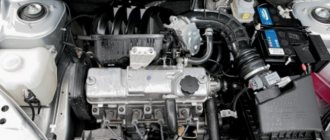
Central locking and its controls - Lada Kalina blog
Now even on the cheapest version, central locking with remote control is standard. Although the manufacturer calls it an anti-theft system, you will agree that it falls short of such a concept. Now, if there were also shock sensors, then we could already talk about anti-theft properties.
So, what we have: the central locking of the Lada Kalina works both with and without a remote control - by simply turning the key in the door lock. The key fob is also the ignition key. There are three buttons on it, on which everything is shown schematically quite clearly and each button performs certain actions:
- Opening doors. When pressed once, only the driver's door opens, the second time opens all the others.
- Closing doors. It is enough to press once for all doors to close at once and the car will be armed.
- Trunk release button - but it does not work in all versions, since to perform this function you need an electric trunk lock.
In addition to external influences, you can control the central locking on Kalina from inside the car. You can close all the doors either using the usual latch from above or thanks to a special button located near the power window control unit on the driver's side.
There is another important function that is designed for the safety of passengers, and to be more precise, small children - this is the locking of the rear doors. To lock the rear doors of Kalina, you need to turn the red chip to the right with the key at its end, on the outside, just next to the lock itself. After this procedure, it will be impossible to open the door from the passenger compartment, so you don’t have to worry about your children; you won’t lose them along the way. It will be possible to open only from the outside, and then again we turn the red chip to the left, to its normal position.
As for the anti-theft alarm function, everything is very simple: no shock sensors, the alarm simply goes off when either one of the doors or the hood and trunk are opened. Frankly speaking, for a domestic car such protection will be quite enough, since they are stolen once every five years.
Fuses and relays Lada Kalina 2 (2013-2018)
Fuse blocks
- Fuse box in the passenger compartment (block of the “old” model - 2013-2015)
- Fuse box in the passenger compartment (block of the “new” model - 2015-2018)
- Fuse box in the engine compartment
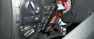
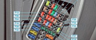
Fuse box in the passenger compartment
To access the mounting block, pull the bottom left corner of the cover to release the left locking point 1, then release the middle bottom point 2 and the two right locking points 3 and 6, then release the top locking points 4, 5 and remove the cover. Installation of the cover is carried out in the following order: first snap the right fastening elements of the cover at points 6 and 3, then snap the lower fastening elements of the cover at points 2 and 1, then the upper ones at points 4 and 5. Make sure that the cover fastening elements fit exactly into the metal latches installed on the instrument panel.
"Old style" fuse box (2013-2015)
| Mounting block 1118 |
| Delrhi mounting block |
| № | A | Protected Circuits |
| F1 | 15 | Ignition coils, injectors, engine control system controller, cooling fan relay (No. 1, 2, 3) |
| F2 | 25 | Norma, Lux: Central body electronics unit, driver's door module |
| 5 | Standard: Daytime running lights | |
| F3 | 15 | Norma, Lux: Automatic gearbox control controller, automatic gearbox control drive |
| 10 | Standard: Hazard Alarm | |
| F4 | 15 | Airbag system controller |
| F5 | 7.5 | Instrument terminal 15 (instrument cluster, engine control system controller, body electronics module, electromechanical power steering, brake pedal switch, speed sensor, automatic transmission selector, windshield wiper switch, rear window defroster switch relay, heated windshield relay ( No. 1, No. 2), seat heating relay, unloading relay) |
| F6 | 7.5 | Standard: Reverse lamps, turn signals |
| 7.5 | Normal, Lux: Reversing lamps, automatic transmission control controller, safe parking system control unit | |
| F7 | 7.5 | Canister purge valve, mass air flow sensor/pressure sensor, phase sensor, oxygen concentration sensors |
| F8 | 25 | Rear window heater, outside mirror heaters (Normal, Lux) |
| F9 | 5 | Side lights on the right side |
| F10 | 5 | Side lights on the left side, instrument and key lights, license plate lights, trunk light, glove box light |
| F11 | 5 | Rear fog lights |
| F12 | 10 | Low beam (right headlight), electric corrector of the right headlight |
| F13 | 10 | Low beam (left headlight), electric corrector of the left headlight |
| F14 | 10 | High beam (right headlight) |
| F15 | 10 | High beam (left headlight) |
| F16 | 10 | Norma, Lux: Right fog lamp |
| F17 | 10 | Norma, Lux: Left fog lamp |
| F18 | 15 | Standard: Cigarette lighter |
| 20 | Norma, Lux: Cigarette lighter, heated front seats | |
| 10 | Norma, Lux: Cigarette lighter | |
| F19 | 20 | Standard: Central locking |
| 7.5 | Norma, Lux ('13→?): Anti-lock brake system (ABS) control unit | |
| 5 | Normal, Lux (?→'15): Anti-lock brake system (ABS) control unit | |
| F20 | 15 | Sound signal |
| F21 | 10 | Fuel pump |
| F22 | 15 | Standard: Front wiper and washer, rear wiper and washer |
| 25 | Norma, Luxury: Central body electronics unit, windshield washer, rear window washer, rear window wiper | |
| F23 | 5 | Instrument cluster, diagnostic connector |
| F24 | 7.5 | Norma, Lux: Air conditioning compressor clutch, automatic climate control system controller |
| F25 | 7.5 | Brake light lamps, interior lamp (Standard) |
| F26 | 25 | Norma, Lux ('13→?): Electronic valves for the anti-lock brake system (ABS) |
| 10 | Norma, Lux (?→'15): Central body electronics unit | |
| Delrhi mounting block | ||
| F27 | 25 | Normal, Lux: Electronic valves of the anti-lock brake system (ABS) |
| F28 | 30 | Standard: Heater |
| 30 | Norma, Lux: Heater, automatic climate control system controller | |
| Mounting block 1118 | ||
| F31 | 30 | Standard: Front door windows |
| 30 | Norma, Luxury ('13→?): Central body electronics unit, short-term activation of high beams, windshield wiper motor | |
| 25 | Normal, Lux (?→'15): Electronic valves of the anti-lock brake system (ABS) | |
| F32 | 30 | Standard: Heater |
| 30 | Norma, Lux: Heater, automatic climate control system controller | |
| Relay | ||
| K1 | Cooling fan | |
| K2 | Norma, Lux: Cooling fan | |
| Standard: Window lifters | ||
| K3 | Starter | |
| K4 | Ignition switch unloading relay | |
| K5 | Standard: Hazard and direction indicators | |
| K6 | Standard: Wiper | |
| Norma, Lux: Heated front seats | ||
| K7 | High beam | |
| K8 | Sound signal | |
| K9 | Low beam | |
| K10 | Standard: Heated rear window | |
| Norma, Lux: Heated rear window and exterior mirrors | ||
| K11 | Engine control unit (main relay) | |
| K12 | Fuel pump | |
| K13 | Standard: Alarm (additional relay) | |
| Norma, Lux: Reversing lamps | ||
| K14 | Standard: Alarm (additional relay) | |
| Norma, Lux: Cooling fan | ||
| K15 | Norma, Lux: Heated windshield | |
| K16 | Norma, Lux: Heated windshield | |
| K17 | Norma, Lux: Air conditioning compressor clutch | |
“New model” fuse box (2015-2018)
| № | A | Protected Circuits |
| F1 | 15 | ’15-’16: Ignition coils, injectors, engine control system controller |
| 15 | ’17-’18: Ignition coils (16-pin), injectors, engine control system controller, cooling fan relay (low speed - if equipped with air conditioning or climate control), cooling fan relay (high speed) | |
| F2 | 30 | '15-'16 (Normal, Lux): Central body electronics unit, driver's door module |
| F2 | 10 | '15-'16 (Standard): Daytime Running Lights |
| 7.5 | ’17-’18: Intake pipe damper valve (VAZ 21127 (16 cells)), canister bleed valve, oxygen sensors, phase sensor (VAZ 21126, 21127 (16 cells)), mass air flow sensor (VAZ 11186 (8 cells) , VAZ 21126 (16-cl.)), automated transmission selector (AMT), control unit for tire pressure monitoring system | |
| F3 | 15 | '15-'16 (Normal, Lux): Automatic transmission control controller, automatic transmission control drive |
| 10 | '15-'16 (Standard): Hazard Alarm | |
| 5 | ’17-’18: Anti-Lock Brake Controller / Stability Control Controller | |
| F4 | 15 | Airbag system controller |
| F5 | 7,5 | Instrument terminal 15 (starter relay, automatic transmission controller, ignition switch unloader relay, heated rear window relay, heated seat relay, heated windshield relay, fuel pump relay, engine control system controller, audio system, electric power steering controller, windshield wiper switch, central body electronics unit, ERA-GLONASS terminal unit, clutch pedal switch (manual transmission), brake pedal switch, instrument cluster, door lock system control unit, driver's door lock switch, air conditioning switch, automatic transmission speed sensor, automatic mode switch transmissions, automated transmission controller (AMT), tire pressure monitoring system control unit) |
| F6 | 7,5 | ’15-’16: Reversing lamps, automatic transmission control controller (Normal, Lux) |
| 7,5 | ’17-’18: Reversing lamps, direction indicators, parking system control unit | |
| F7 | 7,5 | ’15-’16: Canister purge valve, mass air flow sensor (VAZ 11186 (8 cells), VAZ 21126 (16 cells)), pressure sensor (VAZ 21127 (16 cells)), phase sensor (VAZ 21126, 21127 (16 -cl.)), oxygen concentration sensors |
| 10 | ’17-’18: High beam (right headlight) | |
| F8 | 7.5 | '15-'16 (Standard): Turn Signals |
| 10 | ’17-’18: High beam (left headlight) | |
| F9 | 5 | Side lights on the right side |
| F10 | 5 | Side lights on the left side, instrument and key lights, license plate lights, trunk light, glove box light |
| F11 | 5 | Rear fog lights |
| F12 | 10 | Low beam (right headlight), electric corrector of the right headlight |
| F13 | 10 | Low beam (left headlight), electric corrector of the left headlight |
| F14 | 20 | Windshield wiper, steering column wiper switch, windshield washer, central body electronics unit: (windshield wiper (optional)) |
| F15 | 10 | Rear window wiper, rear window washer |
| F16 | 5 | '15-'16 (Normal, Lux): Driver's door module |
| F17 | — | — |
| F18 | — | — |
| F19 | 20 | '15-'16 (Standard): Central locking |
| F20 | — | — |
| F21 | 10 | ’15-’16: High beam (right headlight) |
| 15 | ’17-’18: Fuel pump | |
| F22 | 10 | ’15-’16: High beam (left headlight) |
| 7,5 | ’17-’18: Brake Lamp Switch, Brake Lamps, Auxiliary Brake Lamp, Anti-Lock Brake Controller/Stability Control Controller, Automated Transmission (ATM) Controller | |
| F23 | 10 | '15-'16 (Normal, Lux): Right fog lamp |
| 5 | ’17-’18: Instrument cluster, diagnostic connector | |
| F24 | 10 | '15-'16 (Normal, Lux): Left fog lamp |
| 10 | ’17-’18: Horn relay, horn | |
| F25 | 15 | ’15-’16: Heated front seats |
| 15 | ’17-’18:Cigarette lighter | |
| F26 | 5 | ’15-’16: Anti-lock brake control unit |
| 5 | ’17-’18: Terminal block "ERA-GLONASS" | |
| F27 | 15 | '15-'16: Cigarette lighter |
| 10 | ’17-’18: Right fog lamp | |
| F28 | 15 | ’15-’16: Fuel pump |
| 10 | ’17-’18: Left fog lamp | |
| F29 | 20 | ’15-’16: Central body electronics unit (Normal, Lux), windshield wiper, windshield washer |
| 15 | ’17-’18: Heated front seats | |
| F30 | 10 | ’17-’18: Audio system |
| F31 | 7,5 | '15-'16 (Normal, Lux): A/C compressor clutch, automatic climate control system controller |
| 10 | '17-'18: Central body electronics unit - in variant version (direction indicators, power supply for body electronics unit) | |
| F32 | 7,5 | ’15-’16: Brake light lamps, interior lamp |
| 30 | '17-'18: Central body electronics unit - in a variant version (window lifters, central locking, rain sensor, glove box light, trunk light, interior light unit, daytime running lights) | |
| F33 | 25 | ’15-’16: Anti-lock brake control unit |
| 5 | ’17-’18: Driver door module | |
| F34 | 5 | ’15-’16: Instrument cluster, diagnostic connector |
| 7,5 | ’17-’18: Air conditioning compressor clutch, automatic climate control system controller | |
| F35 | 10 | '15-'16 (Normal, Lux): Central body electronics unit |
| 15 | ’17-’18: Automatic transmission controller, automatic transmission control drive | |
| F36 | 10 | ’15-’16: Sound signal |
| 15 | ’17-’18: Alarm | |
| F37 | 10 | ’15-’16: Audio/Multimedia system |
| 15 | ’17-’18: Central locking (trunk lock switch, door lock control unit) | |
| F38 | 10 | ’17-’18: Daytime Running Lights |
| F39 | 15 | '17-'18: Cigarette lighter in trunk |
| F40 | 10 | ’17-’18: Trailer connection |
| F41 | 50 | ’17-’18: Heated windshield |
| F42 | 30 | '15-'16 (Standard): Power windows |
| 30 | ’17-’18: Heated rear window and mirrors | |
| F43 | 50 | Automated Transmission Controller (AMT) |
| F44 | 30 | Heater, automatic climate control system controller (optional) |
| F45 | 25 | ’15-’16: Rear window defroster |
| 30 | ’17-’18: Front windows | |
| F46 | — | — |
| Relay | ||
| K1 | Ignition switch unloading relay | |
| K2 | Starter | |
| K3 | '15-'16 (Normal, Lux): Cooling fan | |
| '15-'18 (Standard): Wiper | ||
| ’17-’18: Autostart | ||
| K4 | ’15-’16: Cooling fan | |
| ’17-’18: Cooling fan (high speed) - (optional) | ||
| K5 | '15-'16 (Normal, Lux): A/C compressor clutch | |
| '15-'16 (Standard): Turn Signals | ||
| '17-'18 (Standard): Hazard lights and turn signals | ||
| K6 | '15-'16 (Normal, Lux): Heated rear window | |
| '15-'16 (Standard): Front Power Windows | ||
| ’17-’18: Heated rear window | ||
| K7 | High beam | |
| K8 | Sound signal | |
| K9 | Low beam | |
| K10 | '15-'16 (Normal, Lux): Reversing lamps (in configurations with AMT) | |
| ’17-’18: A/C compressor clutch | ||
| K11 | Engine Control Module - ECM (Main Relay) | |
| K12 | Fuel pump | |
| K13 | Seat heating | |
| K14 | Norma, Lux: Heated windshield | |
| '15-'16 (Standard): Hazard Alarm | ||
| K15 | '15-'16 (Standard): Heated rear window | |
| ’17-’18: Alarm | ||
| K16 | '15-'16 (Standard): Hazard Light (Additional Relay) | |
| '17-'18 (Standard): Hazard Light (Additional Relay) | ||
| ’17-’18: Reversing lamps (in configurations with AMT) | ||
| K17 | ’17-’18: Window lifters | |
| ’17-’18: Cooling fan (in autostart mode) | ||
| K18 | ’17-’18: Cooling fan (low speed) - (optional) | |
Fuse box in the engine compartment
| № | A | Protected Circuits |
| 1 | 50 | ’15-’16: Heated windshield |
| 60 | ’17-’18: Generator | |
| 2 | 60 | Generator |
| 3 | 60 | ’15-’16: Generator |
| 30 | ’17-’18: Cooling fan (in configurations without climate control or air conditioning) | |
| 40 | ’17-’18: Cooling fan | |
| 4 | 30 | ’15-’16: Cooling fan (in configurations without climate control or air conditioning) |
| 40 | ’15-’16: Cooling fan | |
| 40 | ’17-’18: Anti-Lock Brake Controller / Stability Control Controller | |
| 5 | 50 | ’15-’16: Electromechanical power steering |
| 25 | ’17-’18: Anti-Lock Brake Controller / Stability Control Controller | |
| 6 | 40 | ’15-’16: Anti-lock Brake System (ABS) Return Pump Motor |
| 50 | ’17-’18: Electric Power Steering Controller |
Video for the article
Location of the fuse box Lada Granta
Fuse box mounting block Lada Kalina
Relay block for VAZ - Lada Granta
CHECKING FUSES+FUSE PANEL LADA GRANT FL 2020
FUEL PUMP DOES NOT WORK/TROUBLESHOOTING KALINA, GRANT DO NOT OPERATE A FUEL PUMP. KALINA GRANT.
Fuses for Lada Granta
Other schemes:
- Fuses and relays Lada Kalina (2004-2013)
- Electrical diagrams Lada Kalina (2004-2013)
- Fuses and relays Toyota Corolla / Auris (2013-2018)
- Fuses and relays Toyota HiAce (2013-2018)
- Fuses and relays Toyota RAV4 (40 2013-2018)
- Fuses for BMW X5 (F15 2013-2018)
- Fuses and relays Lada Granta (VAZ-2190, 2191)
- Lamps used in Lada Granta cars (VAZ-2190, 2191)
- Lada Granta engine control system diagram
- Fuses and relays Ford C-Max (2010-2018)
- Fuses and relays Ford Focus 3 (2010-2018)
- Ford Ranger fuses and relays (T6 2011-2018)
Car electrical wiring diagrams BA3-11183. Lada Kalina Album of electrical circuits
A block with safety devices that allow you to protect equipment in the car’s electrical circuit during possible voltage surges. The connecting connectors for the front, rear harness and instrument panel harness are located under the dashboard on the left side. In particular, the car received: Three power units of different power from 87 hp. Wiring diagram for connecting the instrument panel harness VAZ, VAZ, VAZ 1.
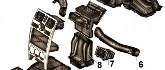
For example, a splitter in a cigarette lighter. Wiring diagram of the rear harness Lada Kalina Connections of the rear harness of the car: 1 - rear harness block to the instrument panel; 2 — block to the wiring harness of the left front door; 3 - to the rear door wiring harness; 4 — right lamp; 5 - to the rear door wiring harness; 6 — to the tailgate wiring harness; 7 - to the instrument panel; 8 — lampshade; 9 — left side direction indicator; 10 — fuel level indicator sensor; 11 — reverse lock switch; 12 - to the right front door; 13 — parking brake sensor; 14 — trunk light; 15 — double-glazed window control unit; 16 — right direction indicator; 17 — left lamp; 18 - to the tailgate.
Generator device - this element is considered one of the main ones, since it allows you to provide power to all devices and equipment of the car while the engine is running. Wiring diagram for connecting the front harness of VAZ, VAZ, VAZ 1,2,3,4-blocks of the front wiring harness to the instrument panel wiring harness; 5 — left headlight; 6 — reverse gear lock solenoid; 7 — reverse light switch; 8-starter; 9 - battery; generator; 11 — blocks of the wiring harness of the battery, starter and front wiring harness; right headlight; electric washer motor; 14 — air temperature sensor; sound signal; 16 - rear window washer electric motor.
If any of the network components fails, then the owner needs to know several aspects: location, switching method, etc. On the same bracket there is a socket with a radiator fan fuse.
It connects the instrument panel harness with consumers in the doors: window lifters, lock solenoids, etc. Buyers could also choose options offered by the automaker, most of which were new products for the domestic auto industry: ABS and ESP systems; Airbag for front passenger; Audio system with touch screen; Navigation system; Rain and light sensors, etc. Wiring diagram for connecting the instrument panel harness VAZ, VAZ, VAZ 1. The fuse or relay has failed.
There is a break in the wiring or a wire has come loose from the device. Photo of the electrical circuit of the headlight corrector For reference: Previously, a hydraulic corrector was installed on cars, but it was considered insufficiently reliable and was replaced with an electromechanical device. Button for opening the trunk in the interior of Lada KALINA - Review
Read more: Insulation resistance in electrical installations is measured
Description of the Lada Kalina wiring diagram
The electrical network of a VAZ Kalina sedan or hatchback is characterized by the use of direct current. Therefore it is single-wire. The voltage level in the electrical system of this car model is 12 volts.
All main components of the on-board network can be divided into several groups:
- energy sources;
- its consumers;
- protective system components;
- controllers, regulators and sensors.
User Rash19 spoke in detail about dismantling the battery on a Lada Kalina car.
Power supplies
Regardless of the configuration, all sources and consumers in the electrical circuit of the Lada Kalina are connected via negative contacts to ground, this is the second cable. The vehicle body is used as grounding. A generator set and a battery are used to power electrical equipment. The battery powers devices and instruments when the power unit is turned off, and the generator - when the engine is running.
If the engine speed is high, the generator unit recharges the battery. While driving, the engine crankshaft begins to rotate the rotor mechanism, which is a moving component of the generator. This allows the mechanical energy generated by the latter to be converted into electrical energy. The rotation procedure of the rotor device is carried out by means of a shaft in bearings installed in special covers. Bearing elements are treated with a special lubricant during vehicle production, the service life of which corresponds to the service life of the generator.
The fixed element of the unit is the stator device, which is secured with four screws to the cover. The generator unit is the main source of electricity in the Lada Kalina car. The voltage from it is supplied to all energy consumers. This unit is equipped with a built-in rectifier device, as well as a regulator.
The stator mechanism includes a three-phase winding. The voltage produced by the unit varies in the range from 14.4 to 15.1 volts. The current limit is 85 amperes. The contact elements of the field winding installed in the rotor are fixed to the copper rings of the shaft by soldering. The generator control device is a non-separable element, which must be replaced if it fails.
Main features of power supplies:
- To protect the vehicle's electrical network from voltage surges, a capacitor device is installed between the ground and the positive valve.
- The battery is an auxiliary source of energy for electrical equipment, allowing the power unit to start.
- A parallel type of connection is used to operate the battery, as well as the generator device.
- The negative output of the battery is connected directly to the car body, and the positive output is connected to the positive terminal B+ of the generator.
- When the engine is running, dismantling the battery is not allowed. This can cause voltage surges, which can damage circuit components.
The “Autoelectrics HF” channel spoke in detail about how to independently dismantle the generator on a Lada Kalina car and repair it.
Protective components
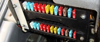
All electrical equipment of the car is protected by two types of elements - relays and fuses.
Safety devices are based on current-carrying components, which, when the current amperage in the electrical circuit increases, fail. Such a switching element is connected in series to the energy consumer and itself destroys the circuit when the load increases. Most of the devices are installed in a separate module installed in the cabin. It is mounted to the left of the steering column, on the center console of the car.
The designation of elements in this block is given in the table.
| Safety device number | Description |
| F1 | Responsible for protecting electrical circuits of several systems at once:
|
| F2 | Power window circuit protection |
| F3 | Light signaling line |
| F4 | Windshield cleaning system, as well as electrical circuits of the rear window heating system switch |
| F5 | Designed to protect system circuits:
|
| F6 | Steering wheel horn fuse |
| F7 | Used to protect:
|
| F8 | Rear window heating system circuit protection |
| F9 | Responsible for the operation of the light source lines in the right headlight and in the same headlamp, as well as for the operation of the glove compartment lighting lamp |
| F10 | Designed to protect circuits:
|
| F11 | Protection of the power line of the fog lamp bulbs in the rear optics |
| F12 | Low-beam light device in the left headlight and motor-reducer for corrector of the lighting flux of this lamp |
| F13 | The fuse is designed to protect the electrical circuit of the low beam lamp in the left headlight, as well as the motor of the corrector device in this lamp |
| F14 | High beam light source in the right headlamp, as well as an indicator light in the instrument panel |
| F15 | High beam light device installed in the left headlight |
| F16 | Light sources in fog lights |
| F17 | PTF light bulb fuse |
| F18 | Protection of the electrical circuit of the seat heating system |
| F19 | Car anti-lock braking system fuse |
| F20 | Protection of the electrical circuit of the heating component of the cigarette lighter |
| F21 | Safety device for the reverse locking line in the transmission |
| F22 | Anti-theft control module |
| F23 | Backup device |
| F24 | Spare fuse |
| F25 | Reserve element |
| F26 | Anti-lock braking system safety element |
| F27 - F30 | Spare fuses |
| F31 | Power line protection device EUR |
| K1 | Optical device washing system relay, designed to protect the device’s electric motor |
| K2 | Installation of electric windows. Used to protect the electrical circuit of the system motor |
| K3 | Starter relay. Designed to protect the traction relay circuit. |
| K4 | Additional element designed for protection:
|
| K5 | Intermittent device for indicators of turning lights, as well as light signaling. Used to protect the electrical circuits of the lighting sources in these headlights. |
| K6 | Windshield cleaning system protection device. Designed to ensure the operation of an electric motor. |
| K7 | High beam relay in head optics. Used to protect light bulbs. |
| K8 | Steering horn device |
| K9 | Relay for protecting power lines for fog optics, intended for lighting sources |
| K10 | Rear window heating system |
| K11 | Heated seat circuit protection relay |
| K12 | Backup relay |
The “Repair and Tuning” channel spoke in detail about independently replacing the fuse box in a Lada Kalina car.
Kalina also has a main module of the motor control system. It is installed under a plastic protective cover in the floor tunnel lining. To gain access to the device, you need to remove the protection from the center console; first pry it off with a flat-tip screwdriver.
Description of elements:
- 1 — block for car diagnostics;
- 2 — device for protecting the power electrical circuit of the main relay;
- 3 - safety element for protecting the fuel pump relay;
- 4 - device for the constant power supply line of the control unit.
An additional module with fuses is installed under the control panel console, next to the control unit.
To gain access you need:
- Remove the right protective cover from the instrument cluster console. It is located next to the front passenger's left foot.
- Unscrew the nut securing the relay module; this will require a socket wrench.
- Pull the bar.
- Remove the system relay module from under the panel.
Description of block components:
- 1 - relay for the electric fan of the cooling system;
- 2 — fuel pump circuit protection element;
- 3 — safety device for the electric engine cooling fan;
- 4 - main relay.
Photo of electrical circuits of modules installed in Kalina.
Priora main fuse block diagram
Motor Control Module
Control system relay block
Electrical circuits of various car parts that are most often in demand
There are often situations when the general diagram does not show the pinout of small car components. Separate graphic images of each, for example doors, foglights, etc., are intended for this.
Pinout of wires of the left driver's door
1 — output to the rear harness: 2 — output for connecting a loudspeaker; 3 - door locking device; 4 — door regulator switch; 5, 7 - supply voltage to switch wiring harnesses; 6, 8 — block of the wire bundle of the switch block; 9 - power supply to the gearbox of the device for lowering and raising the windows.
Passenger's front door wire pinout
1 — output to the rear wiring harness; 2 — output to the right speaker; 3 — door locking device drive; 4 — electric motor of the device for raising and lowering the windows; 5 — bundle of wires for the window regulator control unit terminals; 6 — power window switch key; 7—gearbox of the glass lifting device.
Rear door pinouts
The pinout on the rear doors is the same and has two outputs. One is oriented to connect to the rear “pigtail” of the console wires. The other is needed to supply a signal and power to the door locking device.
Pinout of wires of the cargo compartment door and state sign
1 — electric windshield wiper motor; 2 — auxiliary stop signal; 3, 4 — connection to the rear harness; 5 — gear motor for locking the drive of the cargo compartment doors; 6 — locking device for cargo compartment doors; 7 — heating element of the stern glass; 8 — output to the license plate; 9 — connection from the lighting lamp to the harness of the luggage compartment doors; 10, 11 — lighting element of the state sign.
Graphic images of connecting fog lights
1 - fuse in the assembly block; 2 — immobilizer output; 4 — rear fog lights; 4 — external optics control unit; 5 — ignition switch; A - to power supplies.
Wiring diagram for side lights pins
1 — size lamp in the headlight; 2 — ignition switch; 3 — control lamp of dimensions; 4 — outside light switch; 5 — taillight; 6 — auxiliary brake light; 7 — license plate illumination; 8 — brake light breaker; 9 - fuse in the assembly block; 10 - switch for reverse lights.
Pinout of turn indicators and light signaling
1 — front turn indicator lamps; 2 — sound alarm interrupter; 3 — direction indicator switch; 4 — side direction indicator lamps; 5 — rear turn indicator lamps; 6 — indicators in the instrument cluster; 7 - assembly block, fuses and relays; 8 — ignition switch; A - to the optical regulator; B - to the anti-theft control unit to terminals 23 and 16; C - to the power source.
Electrical circuit for connecting the horn
1 - relay and fuse in the mounting block; 2 — beep button; 3 - horn.
The sound signal circuit is designed regardless of the ignition system, in other words, the horn will work even if the car’s ignition is turned off.
Description of the electrical circuit of the wiper motor
1 - pump in a tank with anti-freeze; 2 — ignition switch; 3 — switch for wiper motor modes; 4 — electric motor for windshield wipers; 5 - assembly block with fuses and relays; A - to the power source.
Designations in the electrical circuit for connecting the engine to the cooling system
1 - electric motor; 2 - resistor; 3 - auxiliary relay; 4, 8 - fuses; 5 — electronic engine control unit; 6 — engine start relay; 7 — main engine start relay; B - to the ignition relay; A - to the battery.
Description of the electrical circuit for connecting the heater motor
1 - fuse and relay in the assembly block; 2 — mode toggle switch; 3 - circuit resistor; 4 — heater electric motor; 5 — ignition switch; A - to the battery.
A complete album with layout diagrams of the electrical equipment of the Lada Kalina car contains a large number of sheets. Graphic images may differ slightly depending on the year of manufacture and model of the car, as well as on the body type - sedan, hatchback. The overview above shows only a small portion of the circuits for informational purposes. The pinout is simple, therefore, anyone who has knowledge of electrical engineering can easily figure out the cause of the malfunction. In addition, the ability to read graphic images will help you introduce additional devices into the electrical circuit, such as an alarm or air conditioner.
The structure of the general electrical equipment diagram of the Lada Kalina car
Kalina's electrical equipment contains all devices that generate, transmit and consume electricity. Of course, all components and assemblies of the car are connected to each other by wires. Wire harnesses are a structure of two or more rods that are connected into a bundle. Sometimes car enthusiasts call them “pigtails” among themselves. The general diagram consists of four main cable bundles interconnected by connectors:
- The harness located in the front part connects the battery to the mounting block and the instrument harness. Next: assembly block with optics unit; starter and generator; reverse breaker at the gearbox.
- The instrument panel bundle combines the front and the rear harness with the “pigtail” of wires of the electronic engine management system, fuses and the instrument panel itself.
- The rear harness connects the instrument cluster with power windows, lock solenoids and other consumers in the doors, as well as the outputs of the rear dimensions, cargo compartment lid, and license plate lights.
- The engine control system bundle is configured to connect to fuses and relays, sensors and instruments. The ECU harness is connected to the dashboard cable bundle.
The connecting connectors of the harnesses, namely the front, rear and tidy, are located under the front console on the left. The heater shaft houses the connecting connectors of the console wire bundle and the “pigtail” of the ECU wires.
Designation of elements on the general electrical diagram
All elements on the diagram have the same pictogram, regardless of brand. Electrical wiring is indicated in one or two colors. Wires of the same color are connected in a separate bundle; a black wire is used for ground connections.
1 — right headlight assembly; 2 — hood locking device sensor; 3 - beep; 4 - starter; 5 - battery; 6 - generator; 7 — electric motor for wipers; 8 — block of contacts for the left headlight; 9 — power window of the front right passenger door; 10 — gear motor for the right door glass lift; 11 — connections to the driver’s door speaker; 12 — locking the left driver's door; 13 — electric drive of the windshield washer reservoir; 14 — outside air temperature sensor; 15 — connection block to the “pigtail” of wires” of the ECM; 16 — electric drive for locking the passenger door; 17 — brake fluid level sensor in the expansion tank; 18 — connections to the speaker of the right door; 19
— passenger door window lift switch, which is located on the driver's door; 20 — switch for lowering and raising the glass of the left door; 21 — blocking the door locking device; 22 — power supply to the front passenger door lift gearbox; 23 — mounting block input; 24 — immobilizer control unit; 25 - similar for security alarm; 26 — instrument cluster pinout; 27 — right direction indicator; 28 — lighting of the “glove compartment”; 29 — glove box lighting switch; 30 — brake light key switch; 31 — ignition switch of the anti-theft system; 32 — external optics control module; 33 — power steering column lever; 34 — left turn indicator switch; 35 — connection block for the right rear speaker; 36 — rear right door lock; 37 — rear window heating unit; 38 — reverse breaker; 39 — reverse switch; 40 — heater fan switch; 41 — additional heater resistor; 42 — electric motor of the stove; 43 — connection block to the left rear speaker; 44 — electric drive for locking the left rear door; 45 — power supply to the fuel pump and float; 46 — reverse light switch; 47 — brake light switch; 48 — cigarette lighter power supply; 49 - power supply for reverse lock; 50 — pads for connecting to a sound reproduction device; 51 — illuminator of the heater ventilation control unit; 52 — power supply to the electric power steering control unit; 53 — power supply for the car interior lighting unit; 54 — right rear lamp; 55 — locking the locking device of the cargo compartment lid; 56 — luggage compartment lighting drive; 57 — license plate illumination; 58 — additional brake lamp; 59 — power supply for heated rear window; 60 — cargo compartment lighting lamp; 61 - rear left headlight.
Which headlights to choose
Factory technology provides for the installation of headlights in a luxury configuration. Indeed, today such products are produced by many manufacturers, large and small.
The following types of products can be found in the retail chain:
- Products under the Bosch brand are always sold as a set (2 pieces) and are distinguished by fairly durable glass and good quality luminous flux. We can say that this is the most reliable option, but its price is noticeably higher than all other analogues.
- Production PTFs are in many ways similar to those described above, but in fact their quality is noticeably inferior to the first option. The only advantage is lower cost.
- Kirzhach fog lights on Kalina have lens-shaped convex glass, which allows you to concentrate the light flux and direct it exactly where it is required. Quite a good and reliable solution.
- Products under the ProSport brand and other similar brands are produced by Chinese factories. It is difficult to judge their reliability and quality, since one option can be excellent, while the second one will fail in a very short time.
Bosch products play leading roles here too
The question of which fog lights are better for Kalina raises a number of disputes, so the decision is yours. As practice shows, the most popular options are Bosch and Kirzhach.
Front wiring diagram Kalina 2
1 – right headlight; 2 – electric motor for washers; 3 – left headlight; 4 – starter; 5 – rechargeable battery; 6 – main fuse block; 7 – generator; 8 – sound signal; 9, 10, 11 – front wiring harness blocks to the instrument panel wiring harness blocks; 12 – air conditioning fan electric motor; 13 – electric fan of the engine cooling system; 14 – ABS hydraulic unit; 15 – right front speed sensor; 16 – left front speed sensor; 17 – front wiring harness block to rear wiring harness block; 18 – right fog lamp; 19 – left fog lamp; 20 – ambient temperature sensor; 21 – reverse lamp switch; 22 – air conditioning compressor; 23 – audible alarm signal; 24 – rear window washer electric motor.
List of contact relays
If we open the main fuse box of Kalina 2, we will see a set of electrical relay housings. There are no other blocks containing relays in the car. We list the elements used in the “Lux” package (21927/21947):
- K1: radiator fan relay;
- K2: relay switching on door locks;
- K3: additional starter relay;
- K4: additional relay (switches current 50A);
- K6: wiper relay;
- K7: relay that turns on the high beam;
- K8: signal relay;
- K9: relay that turns on the low beam;
- K10: rear window heater relay;
- K11: main ignition relay;
- K12: relay turning on the fuel pump;
- K13: additional relay;
- K14: radiator fan relay 3;
- K15: windshield heater relay 1;
- K16: windshield heater relay 2;
- K17: relay that turns on the air conditioning compressor.
The pliers that you will find in the Kalina 2 fuse box will be of two types. “Large” ones are intended for dismantling relays K1-K6, as well as K13-K17.
You can compare the layout of elements in “Lux” and in “Norm/Standard”:
This is how the relays are located in different configurations, 21927 and 21925
Let's consider the data relevant for the “Normal/Standard” configurations:
- K1-K12: as above;
- K13: radiator fan relay 3;
- K14: windshield heater relay 1;
- K15: windshield heater relay 2;
- K16: air conditioning compressor relay.
The last list is also relevant for Kalina Cross Norma. And in more expensive trim levels of the crossover, the “Lux” scheme will probably be used.
Usually, if something electronic stops working in a car, the first thing the car owner should do is check the fuse in the circuit of this device.
The unit is located under the dashboard to the left of the driver's steering wheel.
The location and description of fuses, as well as relays, depend on the version of your new Kalina.
Mounting block complete set Norm 21925 (21945)
Here below is a schematic representation of the location of relays and fuses with symbols.
Explanation of the purpose of each relay:
K1
– Relay for the electric fan of the engine cooling system;
K2
– Door lock relay;
K3
– Additional starter relay;
K4
– Additional relay (50 A);
K6
– Windshield wiper relay;
K7
– Headlight high beam relay;
K8
– Horn relay;
K9
– Relay for low beam headlights;
K10
– Relay for turning on the heated rear window;
K11
– Main relay (ignition);
K12
– Fuel pump relay;
K13
– Relay for electric fan of engine cooling system 3;
K14
– Heated windshield relay 1;
K15
– Heated windshield relay 2;
K16
– Air conditioning compressor relay;
Power supplies Lada Kalina
All cars are equipped with batteries, since this device allows you to start the engine, and it also powers any operating electrical equipment when the internal combustion engine is turned off.
As for the main electrical devices of the system, their list is given below: Ignition switch. By means of a belt drive from the rotating crankshaft pulley, the rotor of the generator unit is driven in a circular motion. The electrical diagram in the manual helps to find a pantograph that has become unusable.
The mounting block is located on the left side of the steering column in the instrument panel under the cover. In particular, the car received: Three power units of different power from 87 hp. Wire breaks and chafing usually occur where there are rubbing or moving parts.
To protect electrical equipment and wires from short circuits, fuses located in the mounting block are used, in addition to fuses protecting the circuits of the engine control system. The wiring diagram contains components that are divided into 4 categories: energy sources; protective components; sensors
Wire breaks and chafing usually occur where there are rubbing or moving parts. Power supplies In the on-board network of the model we are considering, all pantographs operate at a voltage of 12 V and consume direct current.
The connecting connector for the instrument panel harness and the ECU harness is located in the heater shaft. By connecting two or more devices instead of one using a splitter, the load on the node increases significantly. Below is a description of the fuses and relays located in the mounting block.
The electrical circuit for their switching is single-wire. Use only original fuses; using homemade fuses can lead to serious problems. Power supplies In the on-board network of the model we are considering, all pantographs operate at a voltage of 12 V and consume direct current. Wiring diagram for connecting the instrument panel harness VAZ, VAZ, VAZ 1.
PTF wiring for Kalina in color The diagram roughly shows:. Use only original fuses; using homemade fuses can lead to serious problems. If we talk about the sources, then there are two of them in the car: the battery and the generator set. How to Read a Car Wiring Diagram
Location of the relay and fuse mounting block in the “luxury” configuration
Finding the block is very simple; it is located on the left behind the exterior lighting control panel. To get to it, follow these steps:
- pull the tab located to the left of the instrument panel;
- Pull it towards you with a little effort;
- remove the cover.
Let us remind you that all circuits of the engine control system are protected in the form of three fuses. They are located in an additional unit, along with the fuel pump relay and the engine cooling fan. The first is located near the gearshift lever, namely slightly below the ashtray. You can get to it by opening the outer part with a flat-head screwdriver. If one of the fuses breaks, you need to remove it with special tweezers and insert a new one. It is very important that the battery is disconnected. The next block is located to the right of the instrument panel, near the heater air duct under the protective cover.
Note that the hatchback and sedan have different relay systems. However, they are all assembled into a block and installed under the center console. There is also an additional built-in fuse for the electric fan of the engine cooling system. Some owners of the Lada Kalina, for example, in the station wagon configuration, may have problems with the designation.
So, if you have pulled out all the fuses, and when trying to put them in their place, you have difficulties, you will need a multimedia mounting block diagram, since many people with models in various configurations have this problem. It may also be that not all designations are included on the cover, and those that are are not suitable.
It should be noted that fuses have different colors. It, in turn, depends on the current strength for which they are designed. It is important that these figures are observed and in no case exceeded, otherwise there is a high probability of a short circuit. Therefore, when replacing, be sure to use the tweezers that are included in the mounting block.
Main indicators of failure of wiring elements
At the end of the publication, we will also talk about how wiring breakdowns manifest themselves. Sometimes this is noticeable to the naked eye. For example, while driving, your headlight may blink or the lights on the dashboard may flicker. In this case, you need to carefully review the wiring harnesses that are responsible for supplying electricity to the right place. An inspection can provide immediate information about exactly where your car has a problem. But the wires in a car are usually hidden by corrugations, and cutting them is not the best solution. Therefore, diagnostics can be carried out using other methods.
The main manifestations of breakdown of various electrical parts in a car:
- the engine runs unevenly, the speed may fluctuate, it often happens that the idle speed range changes, which is why the car immediately changes its behavior and annoys the owner;
- fuel consumption increases - the ECU or sensors do not work properly, they experience problems and difficulties that cause an increase in consumption due to incorrect signals in the system;
- it is impossible to start the car, in this case you need to look at the electrical parts in the area of the starter, the ignition switch contact group, as well as the wiring between these elements in the car;
- error codes are displayed on the on-board computer screen, and in earlier generations of injection cars the Check Engine lamp lights up, often this is due to the wiring;
- some electrical appliances do not work correctly - the fan does not rotate, the backlight does not turn on, the wipers do not work; these indicators can give you information about electrical problems.
Often in a car, problems with electrical wiring begin with a banal failure of the wipers and flickering lights on the instrument panel. But if such troubles have already begun to occur to you, you can safely expect more serious difficulties. This already indicates that the electrical part of the machine is not working properly and may cause difficulties in the future. At the first symptoms of problems, you should contact a car electrician. At a service station, you will often be immediately offered to change various sensors, relay blocks and fuses. But you need to try to find the problem using conservative methods.
We invite you to watch a video on the topic of electrical wiring in a car:
Kalina wiring diagram
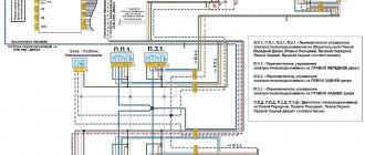
During long-term use of the Lada Kalina, various components may fail. One of these is the electrical circuit of a car, which consists of power sources, instruments, sensors and auxiliary devices. At the moment of failure of any of the elements, it is necessary to know the location, method of connection and purpose of all links in the chain.
In Lada Kalina, the electrical diagram helps to find the location of the required element. Any repair work on existing or connecting new electrical equipment cannot be performed without electrical diagrams. The VAZ 1118 instructions provide diagrams of individual sections of the circuit and are collected in an album. Let's consider the principle of operation of the electrical equipment of the Lada Kalina and the structure of the main electrical circuits.
Electrical diagram of Lada Kalina
Return to contents
Power supplies Lada Kalina
The on-board network of the Lada is characterized by direct current, the nominal voltage of which is 12 V. The electrical circuit of the VAZ 1118 is single-wire. The main elements of the Kalina network can be divided into 4 groups.
- Sources.
- Consumers.
- Protective elements.
- Sensors
Sources and consumers of electrical energy are connected by negative terminals to a metal body (“ground”), which acts as a second wire. Power for all electrical devices of the Lada Kalina car is supplied from two main energy sources: a generator and a battery. While the engine is running, power is supplied to consumers from the alternator. When the engine is turned off, the devices are powered by a battery. While the generator is running, the battery is charged.
A generator is an alternating current synchronous eclectic machine. The rotating crankshaft of the car rotates the moving element of the generator - the rotor. In this way, the mechanical energy of the crankshaft rotation is converted into electricity. The rotor shaft rotates in bearings located in the covers. The bearings are lubricated at the factory with a material that does not require replacement until the end of the generator's service life. The stationary element of the generator - the stator - is tightened with four bolts to the generator cover.
The generator is the main source of electrical energy in Kalina. It supplies power to consumers when the engine is running. The generator is equipped with a built-in rectifier and voltage regulator. The Kalina stator includes a three-phase winding. The permissible voltage range of the generator is 14.4–15.1 V. The gear ratio of the engine to the generator is 1:2.4. The maximum generated current is 85 A.
The fuse box has 28 protective elements. Among them are 4 spare ones with nominal values of 2 A, 7.5 A, 10 A, 20 A. 3 reserve sockets are provided in case of connecting additional fuses. The number of elements is identical for any body type (sedan, hatchback, station wagon).
A relay is a device that closes or opens an electrical circuit when one of the parameters (temperature, pressure, light) reaches an excess value. There are many similar devices in Lada, and they are divided into two separate blocks. The first is the mounting one, consisting of relays and fuses, the second is the unit responsible for controlling the motor.
The mounting block includes relays for the power windows, turn signals, windshield wiper, high beam lamps, horn, rear window defroster and auxiliary relay. Additional features included:
- headlight washer relay;
- fog light relay;
- heating of interior seats.
The power unit control unit consists of an ignition relay, a fuel pump connection and an electric fan. It is located below the central instrument panel. You can get to the relay by removing the right panel of the instrument panel console and unscrewing the fastening nut.
Return to contents
Album of electrical circuits of VAZ 1118
| Elements | Meaning |
| Electric power steering. | 50 A |
| Electric window circuits. | 30 A |
| Heater motor, windshield washer. | 25 A |
| ABS electrical circuits (optional). | 25 A |
| Sound signal. | 20 A |
| Your IP |
| Statistics |
| friends of site |
Click image for a larger view
Electrical diagram of the car: 1 - right headlight; 2 — hood open sensor; 3 — sound signal; 4 - starter; 5 - battery; 6 - generator; 7 — windshield wiper gear motor; 8 — left headlight; 9 — right front door power window switch; 10 — motor-reducer for window lifter of the right front door; 11 — connection blocks to the right front speaker; 12 — electric drive for locking the lock of the right front door; 13 — windshield washer electric motor; 14 — ambient temperature sensor; 15 — block for connecting the wiring harness of the engine control system; 16 — electric drive for locking the left front door lock; 17 — brake fluid level sensor; 18 — connection blocks to the left front speaker; 19 — power window switch for the right front door, located on the driver’s door; 20 — left front door power window switch; 21 — door lock switch; 22 — motor-reducer for window lifter of the right front door; 23 — mounting block; 24 — control unit for the automobile anti-theft system; 25 — security alarm control unit; 26 — instrument cluster; 27 — right side turn signal; 28 — glove box lighting lamp; 29 — switch for the glove compartment lighting lamp; 30 — brake signal switch; 31 — ignition switch with transponder of the automobile anti-theft system; 32 — control unit for external lighting, instrument lighting and headlight beam direction control; 33 — steering column switch; 34 — left side direction indicator; 35 — connection blocks to the right rear speaker; 36 — electric drive for locking the right rear door; 37 — rear window heating switch; 38 — reverse lock switch; 39 — alarm switch; 40 — heater fan operating mode switch; 41 — additional resistor of the heater fan electric motor; 42 — heater fan electric motor; 43 — connection blocks to the left rear speaker; 44 — electric drive for locking the left rear door; 45 — electric fuel pump with fuel level indicator sensor; 46 — reverse light switch; 47 — parking brake warning switch; 48 — cigarette lighter; 49 — reverse lock solenoid; 50 — connection blocks to the head unit of the sound reproduction system; 51 — backlight lamps for the ventilation and heating system control unit; 52 — electric power steering control unit; 53 — interior lamp; 54 — right rear light; 55 — electric drive for locking the trunk lock; 56 — trunk light switch, built into the trunk lid lock; 57 — license plate lights; 58 - additional brake signal; 59 — rear window heating element; 60 — trunk light; 61 - left rear light. This diagram does not show the connection points and wiring harness terminals.
«>
Six problems with electric cars that no one talks about
Electric vehicles have become a hot topic among automakers. Almost all of the world's leading automobile corporations have already announced plans to create and sell electric vehicles; others have already begun implementing the idea of electrifying cars, beginning to saturate the market.
Despite the fact that the concept of electric vehicles was developed more than 100 years ago, the modern electric car has little in common with its distant ancestors in the early days of environmentally friendly automobile manufacturing. Moreover, technologies are constantly improving and developing, so it is extremely difficult to predict what type of future electric cars will transform into and at what stage of development modern representatives of this tribe are.
Now there are several car models on the car market that anyone can purchase for a certain amount of money. Some of them are cheaper, others are more expensive, some appeared earlier, others were introduced not so long ago. Be that as it may, all these developments of electrified cars, whether a hundred years ago or modern models from various automakers, are united by a common concept, which means they have the same pros and cons, adjusted for nuances.
Despite the fact that internal combustion engines surpassed electric motors decades ago, proving their practicality in real life (especially in terms of autonomy and mileage that can be covered on one gas station), the development of electric motors taking into account the specifics of their use in road transport, however, didn't stop.
In many countries, including the USSR, experiments were carried out in this direction, not only prototypes were created for auto exhibitions, no, such cars were produced in limited quantities for testing in real conditions. For example, in the Soviet Union, in various sectors of the national economy, electric models AvtoVAZ, VAZ-2102E served in service (the station wagon was used in postal transportation, delivering breakfast to workers), RAF-2910 minibuses were used as referee cars for the 1980 Olympics, and electric UAZ “Loaves” under the symbol 3801, developed in the late 1970s, generally had unique technical data at that time. The electric van could transport loads weighing up to 800 kg over a distance of up to 75 km, had a regenerative braking system, and it took 1 hour to charge 70% of the battery capacity using an on-board charger. The car ran on alternating current, which at that time was nonsense for such types of cars, foreshadowing the future. Today, almost all types of electric vehicles run on alternating current.
Since then, a lot of gasoline has leaked, the USSR dropped out of the electric car race, but research in the West has not stopped. Electric motors became more compact, their efficiency increased, and in many respects this type of power unit now surpasses many existing internal combustion engines and even those that will appear in the future. Rechargeable batteries also improved their performance, they became more capacious, their dimensions and weight decreased. Development does not stand still.
Below we will analyze not the positive aspects of electric vehicles, which everyone is talking about now, but we will talk about their weaknesses, which, for obvious reasons, automakers prefer to remain silent about.
Types of Software Faults
Software malfunctions of modern computers can be divided into several types:
- BIOS firmware errors. As a rule, they occur quite rarely and can be associated both with the failure of the memory chip itself and with its incorrect user settings. They can manifest themselves in different ways, ranging from the inability to boot the computer to malfunctions in the operation of its individual components, for example, non-functional USB ports or the inability to connect peripheral equipment.
- Operating system and driver errors. They are usually associated either with their incorrect installation or with the actions of malicious software (viruses).
- Errors in application software, for example, office packages or games, which are caused by their incorrect installation, lack of necessary drivers, and the same computer viruses.
When your computer is slow to boot, frequently freezes, reboots, or stops running applications, it's likely a software issue. To find and eliminate the causes of software failures, you should contact only qualified specialists, otherwise you may simply lose your data.
However, often software errors in the operating system itself are a consequence of incorrect operation of computer components, so if you have such problems, it is better to immediately carry out a full diagnosis, since working in this mode can cause the PC to fail, for example, due to overheating of its components.
If problems often arise with client software, most likely the reason lies in incorrectly installed programs, lack of fresh drivers, or incompatibility of this version of the software with the operating system installed on your computer. In most cases, it is enough to simply update the drivers or, carefully monitoring the installation progress and the messages that are issued during the installation.
Why do electrical parts of a car break?
Breakdowns can be associated with a variety of factors. If you buy a used car, there is never a guarantee that it has not been in difficult situations and has not been tinkered with by amateur electricians. Old cars even show constant difficulties with wiring, forcing the owner every now and then to go to a service station and spend quite a lot of money on restoring the car. Electrician work is quite expensive these days.
In new cars, problems are less common, but attention is still worth paying attention to.
The main causes of problems are as follows:
getting the wiring elements wet - in this case, the parts oxidize, causing loss of contact or weakening of the quality of this very contact, this is important to take into account when the car is flooded; old age of wiring parts, which leads to rotting of elements, very often this happens on domestic cars older than 15-20 years, only replacement of parts will help here; oxidation of contacts for other reasons, for example, due to constant condensation in the engine compartment or interior of the car or due to regular temperature changes; rupture of wiring due to careless car repairs or other mechanical damage, the rupture leads to serious problems, and sometimes it will be very difficult to detect them; failure of relays and fuses - in this case, it is enough to replace the element, but also check the condition of the contacts at the place where the part is installed, this is a key point for old cars.
Wiring can fail if inexperienced technicians actively work with it. In this case, the problem is not always revealed immediately. It happens that after poor-quality repairs, the car will drive for a couple of months, and then real problems will begin. The more difficulties that arise, the greater the likelihood that something was done incorrectly during the last intervention in the electrical part. Therefore, it is best to contact specialists whose quality of work you are completely convinced of. Otherwise, problems will be quite difficult to avoid.
Deciphering error codes for Lada Kalina (1st and 2nd generation)
Lada Kalina is already equipped from the factory with a special on-board computer mounted directly into the instrument panel.
Thanks to this, you can react as quickly as possible and diagnose the problem that has arisen. There is a self-diagnosis mode for this.
Unless the previous owner was motivated by selfish goals and “turned out” these bulbs, in which case they need to be replaced.
The video shows entering the diagnostic mode of the on-board computer on the Lada Kalina:
Errors are shown as a digital code and in this article we will tell you how to read them correctly and make the right decision.
Connecting Kalina fog lights
In addition to fog lights and mounts, the kit should include wiring, which is often missing. We recommend that you purchase several meters of wire with a cross-section of at least 0.75 sq. mm. We pull the wires from the engine compartment into the passenger compartment using a piece of wire on the starboard side through the hole above the clutch pedal. To gain access you will need to remove the front left wheel and fender liner.
The most practical places to install the PTF button are in the tunnel, or on the panel instead of the air conditioner button.
A less popular method is to connect the PTF to the light control module (LCM). We fix the relay with a hinged mount in the mounting block.
General diagram of electrical equipment of VAZ 1118
1 — block headlight; 2 — windshield wiper gear motor; 3 - generator; 4 - battery; 5 - starter; 6 — sound signal; 7 — hood open sensor; 8 — power window switch for the right front door; 9 — motor-reducer for window lifter of the right front door; 10 — electric pump for windshield washer; 11 — connecting blocks of wires for connecting the right (front) speaker of the audio system; 12 — electric drive for locking the lock of the right front door with an open door sensor; 13 — ambient air temperature sensor; 14 — connecting block of the wiring harness for connection to the engine control system harness; 15 — electric drive for locking the left front door lock (with an open door sensor and a central locking switch); 16 — sensor of insufficient brake fluid level; 17 — connecting blocks of wires for connecting the left (front) speaker of the audio system; 18 — right front door power window switch (installed on the driver’s door); 19 — left front door power window switch; 20 — central locking switch; 21 — motor-reducer for window lifter of the right front door; 22 — remote control unit; 23 — immobilizer control unit (APS-6); 24 — mounting block; 25 — instrument panel; 26 — right side turn signal; 27 — glove box lighting lamp; 28 — switch for the glove compartment lighting lamp; 29 — brake signal switch; 30 — ignition switch (lock); 31 — lighting control unit; 32 — steering column switches; 33 — left side direction indicator; 34 — connecting blocks of wires for connecting the left (rear) speaker of the audio system; 35 — electric drive for locking the left (rear) door with an open door sensor; 36 — electric heater fan; 37 — additional heater resistor; 38 — heater switch; 39 — alarm switch; 40 — reverse lock solenoid switch; 41 — rear window heating switch; 42 — connecting blocks of wires for connecting the right (rear) speaker of the audio system; 43 — electric drive for locking the right rear door lock (with a door open sensor); 44 — fuel module of the engine control system; 45 — reverse light switch; 46 — parking brake warning lamp switch; 47 — cigarette lighter; 48 — reverse lock solenoid; 49 — connecting blocks of wires for connecting the head unit of the audio system; 50 — backlight lamps on the trim of the center console of the instrument panel; 51 — electric power steering control unit; 52 — interior lamp; 53 — rear light; 54 — block for connecting the electric drive for locking the trunk lid lock*; 55 — luggage compartment lid open sensor; 56 — license plate lights; 57 — additional brake light; 58 — rear window heating element; 59 — luggage compartment lighting lamp.
Wiring diagrams with symbols for Kalina 2 station wagon
The electrical network map in cars made in a universal body includes:
- front cable harness system;
- rear harness diagram;
- instrument cluster wiring system;
- power lines in the rear door.
Front Wiring Harness Diagram
Description of the components:
- 1 — right lighting device;
- 2 — electric motor of the washer system;
- 3 — left lighting device;
- 4 - starter;
- 5 - battery;
- 6 — main module with safety devices;
- 7 - generator unit;
- 8 — steering horn;
- 9 — connector for connecting the front wiring harness to the instrument cluster;
- 10 — conductor block for connecting the previous harness to the control panel;
- 11 - similar connector;
- 12 - electric motor of the climate system ventilation device;
- 13 — fan of the power unit cooling system;
- 14 — hydraulic unit of the anti-lock braking system;
- 15 — speed controller installed on the front left;
- 16 — speed measurement sensor, located on the left front;
- 17 — harness connector with wires for connecting the front harness to the rear block;
- 18 — right fog lamp;
- 19 — left PTF;
- 20 — controller of air temperature level in the environment;
- 21 — automatic transmission control sensor, installed only on Kalinas with automatic transmission;
- 22 — compressor unit of the air conditioning system;
- 23 — alarm sound signal;
- 24 — electric motor for the rear window washer system;
- 25 — automatic transmission;
- 26 — connector for connecting to automatic transmission;
- 27 — output for connection to the automatic transmission selector switching device;
- 28 — block for connection to the automatic transmission speed controller.
Wiring diagram of the front wiring harness Kalina 2 station wagon:
Left part of the front harness diagram
Right side of the front harness diagram
Rear wiring diagram
Description of components:
- 1 — output for connecting the rear cable harness to the connectors going to the instrument cluster;
- 2 — block of the wiring harness connecting the rear to the instrument panel;
- 3 — right side turn signal headlight;
- 4 — left side turn signal;
- 5 — parking brake controller, designed to output a signal to the dashboard;
- 6 — rear harness connector with cables connected to the contact elements in the tailgate;
- 7 — lighting module in the car interior;
- 8 - switching device in the seat belt installed on the driver's seat;
- 9 — luggage compartment lamp;
- 10 — control unit for electric fuel pump;
- 11 — right lighting device;
- 12 — connector of the rear cable harness for connection to the contact elements of the conductors in the tailgate;
- 13 — left lighting device;
- 14 — connector for connecting the rear cable harness to the conductor block installed in the rear left door;
- 15 — output of the rear wiring harness for connection to the cables of the right door;
- 16 — block of the rear wiring harness for connection to the connector installed in the front door on the right;
- 17 — rear harness connector with wires, designed to connect the front harness installed in the left door;
- 18 — control module for airbags;
- 19 — harness connector with rear block conductors for connection to the front harness output;
- 20 — rear harness connector with cables for connecting to the output of the parking system controllers;
- 21 — control module, as well as a microprocessor unit for the parking safety system signaling device;
- 22 — switching device for parking radar;
- 23 — sound speaker of the safe parking system;
- 24 - switching device for the interior lighting system, installed in the driver's door pillar;
- 25 — switch for the lamp located in the front passenger door pillar;
- 26 - a similar device for a lighting fixture installed in the door pillar located at the rear right;
- 27 — switch for the interior lighting system, installed in the rear left door pillar;
- 28 — device for activating and disabling the right seat heating system;
- 29 — switch for turning on and off the heating device on the left seat;
- 30 — right seat heater;
- 31 — heating device located on the left seat;
- 32 — pre-tensioning mechanism of the driver’s seat belt;
- 33 — a similar device for the front passenger;
- 34 — main body electronics module;
- 35 — controller of the automatic glass cleaning system — rain sensor;
- 36 - control device for changing the sensitivity level of the rain controller;
- 37 — connector of the harness with cables for connection to the block installed on the instrument cluster;
- 38 — right rear speed controller;
- 39 - speed detection sensor, installed at the rear left.
Wiring diagram of the rear wiring harness Kalina 2 station wagon:
Left side of the rear harness diagram
Right side of rear harness diagram
Instrument panel wiring diagram
Main components of the circuit:
- 1 — connector of the instrument cluster harness for connection to the output of the front block;
- 2 - similar output;
- 3 — control panel harness connector for connection to the rear block output;
- 4 - the same connector;
- 5 — lighting control unit;
- 6 — ignition switch;
- 7 — switching device for control unit modes;
- 8 — switch for activating and disabling the windshield wiper system;
- 9 — dashboard;
- 10 - switching device for activating and disabling the alarm;
- 11 — switch for the drive mechanism of the trunk door lock;
- 12 — diagnostic connector;
- 13 — control panel harness output for connection to the air supply module cable block;
- 14 — switching device for the rear window heating system;
- 15 — button for activating and disabling the light alarm;
- 16 — brake signal switch;
- 17 — audio system;
- 18 — block for connecting the radio;
- 20 - rotating mechanism;
- 21 — airbag unit for the driver’s seat;
- 22 — steering horn switching device;
- 23 - safety module in which the relays are located;
- 24 - electric power steering;
- 25 — cigarette lighter;
- 26 — glove compartment lighting device;
- 27 — switching mechanism for the glove box lighting system;
- 28 — output of the harness with cables of the control panel for connection to the block of the harness with wires of the ignition system;
- 29 — sensor of the power unit control system;
- 30 — output of the harness with cables going from the control panel to the rear harness block;
- 31 — electronic gas pedal;
- 32 — controller for changing the rotation speed of the electric motor of the heating system;
- 33 — electric motor of the stove;
- 34—solar radiation measurement controller;
- 35 — switching device for the exchange rate stability system;
- 36 - relay for the electric motor of the cooling system of the power unit;
- 37 - compressor device relay;
- 38 — protection element for the electrical circuit of the windshield heating system;
- 39 — relay for the heated windshield system;
- 40 — controller for changing the illumination level of the optics;
- 41 - additional relay;
- 42 — airbag unit for the front passenger;
- 43 — temperature level controller of the evaporation device;
- 44 — sensor for determining the steering angle;
- 45 — windshield heating device;
- 46 — additional heating element;
- 47 — switching device for the windshield heating system;
- 48 — main body electronics control module;
- 49 — gearmotor device for the air flow distribution mechanism damper;
- 50 — drive device for controlling the gear shift mechanism;
- 51 — climate system control sensor;
- 52 — gearmotor device for mixing air flows;
- 53 - electric motor for the drive device of the recirculation system flap.
Electrical diagram of the instrument cluster Kalina 2 station wagon:
First part
Second part
The third part
Rear Door Harness Wiring Diagram
Description of components:
- 1 — contact elements of the rear door wiring harness, connected to the front connector;
- 2 — output of the rear additional harness, connected to the cables of the rear license plate lighting devices;
- 3 — gearmotor device for the electric drive mechanism of the trunk door lock;
- 4 — arrangement of the rear window heating system;
- 5 — gear motor mechanism for the rear window cleaning system;
- 6 — locking device in the luggage compartment door;
- 7 — contact elements of the harness installed in the rear door and connected to the rear output connector.
- 8 - additional brake signal device.
Wiring diagram for the rear door in the station wagon
Removing and installing the control unit for the standard alarm system on Kalina
Disconnect the negative terminal from your vehicle's battery.
To perform this repair, you will need a minimum of equipment and tools. The list of what you need is given below:
- crosshead screwdriver
- Head for 10
- Driver or ratchet
- Extension
So, first you need to unscrew the 4 bolts securing the plastic sill trim:
After this, freely remove this decorative trim:
Now you can start removing the floor covering, but there is no need to remove it completely. Simply lift it halfway to gain access to the alarm unit.
Now that you can remove it, you must first disconnect the plug with the wires. To do this, on the left side you need to press the plastic lock of the plug and pull it to the side:
In the end, this is the final result:
Now all that remains is to unscrew the two nuts securing the alarm unit itself through the holes, as shown in the photo below:
And the final step in this repair will be to remove the module from its seat:
If replacement is necessary, install this part in the reverse order of removal. This work is completed within 10 minutes and is not difficult.
Kalina 2 panel photo
It has become known what the panel of the new second generation Kalina will look like. The photographs are fundamentally different from those presented at the 2012 Moscow Motor Show.
The first 40 pre-production Kalina 2 cars were also photographed
Discussion of all photos here
We recommend watching:
But it seems good,))) except for the seagull TV! Normally, it’s interesting what and most importantly at what price it will be!
The question is, should I wait or should I take it now? Cabin 1
Typo Kalina 1
The car is beautiful, but what will the price be... The photo shows a luxury one, with air conditioning
But the dashboard doesn't show engine temperature.
The torpedo designer was clearly tipsy.
Uzhasssss(((Although what else could you expect from AvtoVAZ(((We just have to wait until they fix the package again and remove everything from there, put a regular airbag instead of an airbag, tape it to the steering wheel...(they will tell our people it will go like this))XDDD
Nikolay, you shouldn’t waste all this nonsense on AvtoVAZ. They began to do things normally. I've been driving Kalina for 5 years and I'm happy with everything. But the pre-restyling torpedo was made in one rather successful style, but here I see some kind of crazy set of elements from different cars in different styles. The green backlight of the tidy in combination with the purple backlight of the air conditioner knob is especially killer - that’s a “five”! And this two-din “TV” is stupid. Most Kalina buyers install budget single-din radios and I can hardly imagine how they will look in this frame with a visor. It looks like it was made for CarPC.
My friend practically cut off a Nexia on a viburnum at a speed of 60 km/h. I got away with minor repairs of about 30 thousand, the Nexia cannot be repaired. I myself drove a Kalina for 5 years - not counting consumables for maintenance, I spent about five thousand, the mileage is 118 thousand. I would never take NEXIA, I rode with a friend.
Ignition circuit Kalina 2
1 – oil pressure warning lamp sensor; 2 – generator; 3 – throttle pipe with electric drive; 4 – coolant temperature sensor; 5 – ignition system wiring harness block to the instrument panel wiring harness block; 6 – solenoid valve for purge of the adsorber; 7 – air conditioning system pressure sensor; 8 – mass air flow sensor; 9 – crankshaft position sensor; 10 – oxygen concentration sensor; 11 – controller; 12 – diagnostic oxygen concentration sensor; 13 – blocks of the wiring harness of the ignition system and the wiring harness of the ignition coils; 15 – ignition coils; 16 – spark plugs; 17 – nozzles; 18 – blocks of the wiring harness of the ignition system and the wiring harness of the injectors; 19 – phase sensor; 20 – knock sensor.
Fuses, list and description
The electrical circuit of the Kalina-2 car can contain up to 38 fuses in total. The block installed under the hood contains 6 fuses designed for significant current. We, in turn, will consider the diagram of the main block:
All fuses in the electrical circuit of Kalina-2
- F1, 15A: ignition, injectors, power supply to the ECU and radiator fan relay;
- F2, 25A: power supply to the TsBKE unit and the front left door module;
- F3, 15A: electric drive of the automatic transmission, also power supply to the automatic transmission ECU;
- F4, 15A: power supply for airbag assembly;
- F5, 7.5A: speed sensor, brake pedal sensor, power supply to the instrument panel and ESD, ECM controllers, power supply to the automatic transmission selector, voltage on the windings of the unloading relay and the relay of the glass and seat heaters, power supply to the body electronics unit, washer switch;
- F6, 7.5A: power supply for automatic transmission electronics and reverse lamp relay;
- F7, 7.5A: voltage at the canister purge valve, at the phase sensor, mass air flow sensor, DC;
- F8, 25A: rear window heater and mirror heater circuit;
- F9, 5A: all “dimensions” on the right;
- F10, 5A: all “dimensions” on the left, license plate lights, keys;
- F11, 5A: rear fog lights;
- F12, 10A: low beam lamp, electric corrector for the right headlight;
- F13, 10A: low beam lamp, electric corrector for the left headlight;
- F14, 10A: high beam lamp on the right;
- F15, 10A: high beam lamp on the left;
- F16, 10A: “fog light” on the right;
- F17, 10A: “fog light” on the left;
- F18, 20A: seat heater circuit and cigarette lighter circuit;
- F19, 7.5A: ABS controller power supply;
- F20, 15A: signal;
- F21, 10A: fuel pump motor;
- F22, 15A: windshield and rear window washers, rear wiper;
- F23, 5A: power supply to the diagnostic connector, as well as to the instrument panel;
- F24, 7.5A: air conditioner motor-compressor clutch circuit, power supply to the air conditioner controller;
- F25, 7.5A: voltage at the brake pedal sensor;
- F26, 7.5A: ABS valve drives;
- F31, 30A: short-term switching on of high beams, power supply to the central bank, gear motor for front wipers;
- F32, 30A: heater fan circuit, power supply to the air conditioner controller.