VAZ 2101 vehicles are equipped with a contact battery ignition system. The task of this system is to timely supply a spark to the engine cylinders to ignite the fuel mixture.
Next, we will consider the general design and individual elements that make up the VAZ 2101 ignition system.
It includes an ignition coil in which a high-voltage pulse is formed, a distributor-breaker (also known as a distributor) that distributes the pulse among the cylinders, spark plugs that provide a spark in the cylinders, an ignition switch that turns on and off the power supply to the coil, and a battery - a source of electricity. , conventional wiring and high voltage wires.
1 - Ignition switch, 2 - Ignition coil, 3 - Ignition distributor, 4 - High voltage wires, 5 - Spark plug, 6 - Capacitor, 7 - Battery, 8 - Voltage generator, 9 - Distributor rotor, 10 - Cam mechanism, 11 -Breaker contacts
Ignition coil
The coil is sealed with an open-type magnetic circuit, filled inside with oil for transformers. Its model is B.117A. The body of this element is aluminum, hermetically sealed on top with a plastic lid.
Designation names
| 1. | Ceramic insulator | 10. | Frame |
| 2. | Frame | 11. | Power connection terminal |
| 3. | Insulation special paper | 12. | Contact spring |
| 4. | Primary winding | 13. | Primary winding housing |
| 5. | Secondary winding | 14. | External primary insulation windings |
| 6. | Insulation | 15. | Mounting clamp |
| 7. | Primary terminal windings | 16. | External magnetic circuit |
| 8. | Contact screw | 17. | Core |
| 9. | Center wire terminal |
The VAZ-2101 ignition coil is essentially a two-winding transformer:
- primary winding of 300-400 turns (wire cross-section - 0.7-0.8 mm),
- secondary winding - 20-30 thousand turns (wire cross-section - 0.1-0.7 mm).
Coil operating principle
When the contacts of the distributor open, the magnetic flux created by the battery decreases sharply. Passing the magnetic circuit and windings, the electromagnetic flux creates a self-induction emf of 200-300 V on the primary winding and over 10 kV on the secondary. The voltage from the secondary winding is supplied to the spark plugs to create a spark.
Electronic ignition design
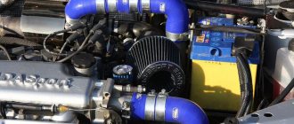
To install a contactless system on a “classic” VAZ 2107 with a carburetor, it is advisable to study how it works. This will help you correctly assemble the circuit and successfully put it into operation. BSZ for old carburetor Zhiguli models consists of the following elements:
- distributor, also known as the distributor of the ignition system;
- high-voltage coil of a new design (different from the old one, which works with mechanical contacts);
- switch responsible for system management;
- high-voltage and ordinary wires with connectors and terminals connecting the listed elements;
- spark plug.
Reference. Since the new ignition system does not have a contact group, and its operation is controlled by an electronic unit, the names “contactless” and “electronic” are equally suitable for it.
Elements of the electronic ignition system of the VAZ 2107
The new high-voltage coil has 2 windings. The primary one is made of a large cross-section conductor and is connected to the vehicle's electrical network through the ignition switch relay. The secondary winding is wound with a large number of turns of thin wire and connected by a high-voltage wire to a distributor consisting of the following parts:
- a housing with a centrally mounted shaft;
- a movable contact (the so-called slider) is fixed at the end of the shaft;
- A cover is placed on top of the body, where high-voltage large-section wires leading to the spark plugs are connected;
- there is a protrusion (cam) on the shaft, opposite which there is a Hall sensor;
- a vacuum diaphragm is attached to the side, providing ignition advance.
The switch is connected by small cross-section conductors to the distributor and coil; its task is to control the timely supply of sparks to the spark plugs.
Reference. In newer modifications of the VAZ 2107, where there is an injector instead of a carburetor, there is no separate switch. There is no need for it, since the on-board computer controller is in charge of spark generation and fuel supply.
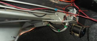
Connection diagram of contactless system elements
Distributor
On VAZ 2101 models until 1980, a distributor (distributor) of the R-125B model was used. Its peculiarity was the absence of a vacuum regulator; there was only a mechanical type octane corrector, which made it possible to slightly change the ignition timing (IZ).
Beginning in 1986, together with the installation of the Ozone carburetor, a distributor equipped with an OZ vacuum regulator (model 30.3706), the design of which is described below, began to be installed on VAZ engines.
Model 30.3706 consists of a distributor, a breaker and two regulators - centrifugal and vacuum.
The distributor ensures the distribution of coil pulses among the spark plugs in accordance with the operating order of the power plant.
It consists of a rotating rotor and fixed segments located in a plastic cover. There are two contacts on the rotor - central and side, with an interference suppression resistor attached between them. A graphite electrode is pressed from above to the central contact; for better contact, pressing is carried out by a spring.
The distributor works like this:
the voltage from the secondary winding is supplied to the rotor, then through a spark gap of approximately 0.5 mm it enters one of the segments of the distributor cover, then through high-voltage wires to the spark plug, which ensures the appearance of a spark.
The breaker ensures that the electrical circuit opens at the right time. Its design includes a cam washer with edges and a contact post. The edges of the cam washer are specially shaped to ensure quick opening of the contacts, smooth closing of the contacts and absence of rattling.
The rotating cam alternately closes and opens the contacts, thereby interrupting the voltage supply to the primary circuit of the coil.
The breaker and distributor must work synchronously with the crank mechanism. To ensure synchronization, the cam washer and rotor are located on the same shaft, and are driven by the camshaft.
Centrifugal regulator – provides a change in the angle of rotation in accordance with the rotation of the knees. shaft
A plate with movable weights is welded to the top of the cam bushing. With increasing knee speed. shaft, the weights move apart due to centrifugal force, turning the plate together with the cam in the direction of shaft rotation. This ensures earlier opening of the contacts (increasing the angle of contact).
Vacuum regulator – adjusts the OP angle depending on the load of the power unit and the position of the throttle valve.
It is attached to the distributor and includes a housing and a cover. The body is divided by a plastic membrane into two cavities, one of the cavities is connected to the throttle space in the carburetor, and the second to the atmosphere. The membrane can act on the breaker through traction.
As the load decreases, the filling of the cylinders with the combustible mixture and the pressure during ignition decreases, and this requires an increase in the angle of ignition. To do this, the membrane bends (under the influence of a pressure difference) and rotates the breaker to the desired angle.
Instructions for setting the ignition
If you strictly followed the instructions, connected all the wires according to the diagram and did not misalign the marks, then the motor will start without problems. To adjust the ignition, you need to ensure stable engine operation, so first warm it up for a few minutes, without letting it stall by pressing the gas pedal.
Advice. If the engine does not start successfully, and when you turn on the starter there is not even a popping sound, then you probably made a mistake with the wiring. Check everything again according to the diagram included with the factory set of electronic ignition parts.
Adjustments can be made on a warm engine using two methods:
- without the use of special devices - “by ear”;
- fine adjustment using a strobe light.
A strobe is a device with a light bulb that flashes simultaneously with the transmission of a pulse by the Hall sensor. When the switched on strobe is brought to the crankshaft flywheel with the engine running, the position of the notch becomes visible. Hence the possibility of precise adjustment.
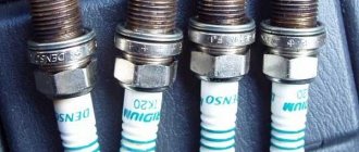
Spark plug
The VAZ-2101 used Soviet spark plugs of the A17DV brand, but now, when the market is filled with high-quality foreign-made brands, you can easily choose spark plugs with much better characteristics, the main thing is not to fall for a Chinese counterfeit.
Design features of candles
The length of the threaded part of the spark plug is 19 mm, with a pitch of 1.25. The hexagonal part (for the spark plug wrench) is made with a size of 20.8 mm.
The permissible gap between the spark plug electrodes is checked with a probe. According to the book, with a contact system, the gap of the VAZ 2101 spark plug should correspond to 0.5 - 0.6 mm.
Communities › VAZ: Repair and Modification › Blog › Will a spark ignite a flame? Not always!
This modification will be useful in almost the entire line of VAZ injection engines.
Just a word of caution - based on the results of comments and questions. ! ! ! Intervening and making changes to the electrical circuit of a car requires at least basic skills in electrical engineering and awareness of the actions being performed! ! ! If you feel that electrical circuits and car electrics are a little out of your profile, contact a more qualified person or an experienced auto electrician. This is in your own interests. And it will save you from unpredictable consequences.
In order. Engine VAZ 21124. 1.6 liters, 16 valves. Individual ignition coils (or dual module with high-voltage wires). Everything is beautiful. And at first glance, it seems that everything is thought out, so it should work clearly and reliably. It turns out that this is far from true. This is a VAZ!
Quite a lot has been written about ignition problems on this engine - about the choice of spark plugs, replacement and selection of individual ignition coils (hereinafter - IKZ).
So I came face to face with this problem.
The main manifestations are that the engine rotates unevenly at idle (speeds dance in the range of approximately 720-840 rpm), sluggish acceleration with twitching, increased consumption. In principle, most people understand that misfires are rare, but they do happen. The ECU doesn't see them directly. Last year, one coil clearly started to fail - the ECU saw it. I replaced it and it started to loosen up a bit. But still the engine was missing something. What a good spark! Here's more about this. From the versions: - replacing the spark plugs (the current NGK ones lasted only 7 tons km) with something more expensive from the “platinum, iridium” series, etc. - an expensive option. — changing the IKZ, and they are a little over 7 years old (the original ones are BOSHevsky, the mileage is 75 tkm) - it’s a little expensive (the cost of one IKZ is around 540 UAH ($22), and there are four of them) and there is no confidence that the problem will go away. — Mass air flow sensor, which is also not fun... — look into the ECU to check the serviceability of the keys, current-limiting resistors, etc. Acting at random or based on assumptions is not my method or my approach.
Reading the ECU showed: 1. Speed jumps 2. Injection time jumps, slightly 3. Reduction ratio jumps at idle (9-15 degrees) - a bit too much 4. Power supply, MVR, TPS - everything is stable and beautiful.
5. ECU masses - everything is ideal (previous modifications and correct wiring were made) Verdict - unstable sparking.
The ICP parameters were measured - the resistance of the primary winding, inductance, the resistance of the secondary winding (taking into account the diode in the high-voltage circuit), checking for the absence of short-circuited turns - the norm.
The coils have a minimal (± 2%) spread and nothing alarming in the parameters. More on this later. On a hastily assembled “stand” there is a normal spark, a little weaker in appearance than on a classic with a contactless ignition system, but still clear throughout the entire range of rotational speeds (2 - 45 Hz), with an accumulation time of 2.0 ms. The coils are live. The rubber caps in the explosive part of the coil have been replaced. To complete the picture, I decided to look at the diagrams on the coils with an oscilloscope on the engine, pulled out my C1-65A - a reliable, proven workhorse to the machine and off I went. The ignition is on. The engine is running. On board the network (to the battery) 14.35V, which at XX, one hundred at 2000 rpm is stable. Amazing! Let's see. As usual, I start with power to the coils (+12V from the ignition switch) and I’m HORROR! On the coils, as well as on the IKZ harness connector, the ripple is exactly 2.5V. I was not mistaken, I measured it in 2 modes (and the oscilloscope has been an everyday tool for many years and not the only working tool - there is no room for doubt). I apologize for the bad photos - the scan is slow and the shutter speed in the camera is short.
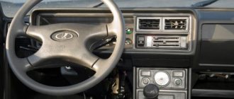
Ignition switch VAZ 2101
Includes a housing with a locking mechanism, an anti-theft mechanism and a contact part.
If the locking mechanism or anti-theft mechanism breaks down, the lock is completely replaced. The contact part is secured with a locking ring in the housing, and if it malfunctions, it can be replaced separately.
Article on the topic - Design and replacement of the ignition switch