Almost all new cars use the body as the main source of electrical energy. Figuratively speaking, the car body is a single wire that has a negative charge, used by all electrical devices in the car that consume energy. For this reason it is called mass, or in other words minus. For this reason, if poor contact with the ground occurs as a result of oxidation or poor fastening, problems arise in the operation of the vehicle, the functioning of the equipped electronics, or problems with the engine appear.
Where can the engine mass be located?
In almost 100% of modern cars, the body is used as a single source of electrical energy.
The car body is like a universal wire with a negative charge for all consumers of electricity. That is why the body is called the painfully familiar term “mass”. Why “painfully familiar”? Yes, because if somewhere the contact with the mass is either poorly secured or oxidized, the inexplicable begins. Let’s take the first example we come across: the sore subject of the first and second Samaras is the blinking of yellow and red headlights, etc.
I have already analyzed this situation in the article: why the headlights do not light up, where I made a “mass”, as the main reason for unstable operation. But the headlights are a small thing compared to the performance of the engine and the electronic engine control system (ECS). In this article we will look at the weak “mass” points on the VAZ 2114 2113 2115 with 1.5l, 1.6l engines.
Engine instability. What is “mass” and how to find it
Almost any car model is created according to the principle that its body is assigned the role of a single source of electricity. In other words, it is the base conductor with a negative charge to which all electrical appliances are connected. Thus, the weight of the Samara and other car models is attached specifically to the body. Having understood this principle, it is much easier to calculate the causes of many problems associated with the car’s power supply. For example, quite often the Samara breaks down, which is reflected in the blinking of the headlights. However, a poor ground connection of the VAZ 2115 can cause much more serious damage, primarily related to engine operation and the electronic control system. This article will indicate the weakest points of VAZ cars in the context of working with “mass”.
How to find the location of a mass
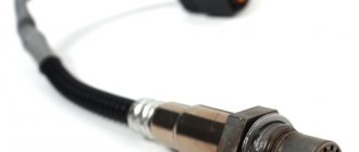
BatteryAs a minus, a car battery has two conductors: one thin, the other thick. The role of the thick wire is to secure the ground in the VAZ 2114 from the battery negative to the motor housing. A faulty contact in this area leads to a decrease in charge transfer from the battery, a drop in starter power, and ECM problems.
To make sure that the ground is properly connected to the engine, you need to inspect the two fastening nuts that secure the contact to the engine housing. To do this, slightly loosen the outer nut and tighten the inner nut, after which we apply additional tension to the outer one. The role of the thin wire is to connect the battery to the area of the car body in the immediate vicinity of the battery. This conductor is a single source for all electrical appliances in the car. The process of checking contact is also carried out by tightening the nut near the terminal and near the body. ECM
Battery weight
The “minus” on the battery has two branches: a thick wire and a thin one. A thick wire runs from the battery negative to the engine housing. If this contact is not secured properly, then the battery is not fully charged, the starter does not develop full power, and the ECM stalls (since it takes weight from the engine).
On the negative mount of the battery with the engine, you need to check the tightness of the two nuts between which the contact to the engine is attached: first of all, loosen the outer nut and tighten the inner one, and then tighten the outer one.
The second wire from the battery is much thinner and is attached to the body next to the battery itself. This wire is the source for all energy consumers in the car. Here you also need to check the tightening torque of the nut both to the body and to the battery terminal.
Weight in the VAZ 2114: location, possible problems and their solution
The vehicle's electrical network is connected to a common “minus”, or mass, which is the entire body. That is, the body as a mass on the VAZ 2114 represents a single source of negative charge. And the source of negative charge is the connection between the case and the negative terminal of the battery.
If the wires connected from the electrical network to ground oxidize (come off), problems arise with the electronics, engine or control system. In case of typical “mass” faults, for example, “blinking” of the rear lights instead of turning on the turn signal or poor cranking of the starter, first check the condition of the wires connected to ground and contact points.
Where is the mass of the ecu for the VAZ 2114
The first ground pin from the ECU on cars with a 1.5 engine is located under the instruments on the power steering shaft mount. The second terminal is located under the instrument panel, next to the heater motor, on the left side of the heater housing.
On cars with a 1.6 engine, the first terminal (mass of the VAZ 2114 ECU) is located inside the dashboard, on the left, above the relay/fuse block, under the sound insulation.
The second terminal is located above the left screen of the center console of the instrument panel on a welded stud (fastened with an M6 nut).
All studs have no corrosion protection other than factory paint. When the paint comes off, the stud rusts. Pay attention to the condition of the stud and treat it with protective lubricant.
Where is the ECM mass located?
The ECM ground is located on the plug mounts on the right side of the 1.5 engine head. On the 1.6 engine, the mass on the VAZ 2114 engine is placed on a welded pin connecting the metal frame of the central panel and the floor tunnel.
Where is the battery mass located?
The battery mass consists of two wires of different thicknesses. A thick wire extends from the battery negative to the engine housing. A thin wire is attached to the housing next to the battery.
Problems with bulk wires
How do problems with ground contacts manifest themselves?
Engine
If the ground wire from the ECM is oxidized or disconnected, this manifests itself in a spontaneous change in operating modes or the car suddenly stalls. Poor contact from the torpedo causes unstable engine operation at idle.
If the contact is broken, the battery charge deteriorates, the starter speed decreases during startup, problems arise in the ECM, because the second ground wire from the battery goes there. To correct the violation, first check the tension of the nuts securing the thick wire to the engine.
To do this, the outer nut is loosened, the inner nut is checked and, if necessary, tightened. The outer nut is then screwed back on. The thin wire is the main conductor of the negative charge. In case of malfunctions, check its condition and the tightness of the nut on the housing, as well as the bolt on the battery terminal.
ECM weight
For SAMAR with a 1.5 liter engine, the mass for the ECM is taken from the engine housing, from the fastening of the plugs . The plugs are located on the right side of the block head.
For SAMAR with a 1.6 liter engine, but also 1.5 liter engines, which have a new generation ECM (Bosch 7.9.7, January 7.2), the weight of the ECM is taken from a welded stud. The pin is attached to the metal frame of the instrument panel to the floor tunnel (under the ashtray). In practice, it happens that this pin is painted at the factory and is loosely tightened. Therefore, over time it may become loose and at the moment the fan is turned on, there will be a drop in the voltage of the following sensors (which will lead to jumps in speed): DTOZH, TPS, MAF.
Where is the mass located?
When operating a car, it is important to know all the places where the mass of the VAZ 2114 engine is located. If a malfunction occurs in this direction, you can quickly detect the source of the problem and eliminate it accordingly. So, where is the mass of the ECU for the VAZ 2114? Let's try to understand this issue.
Where is the mass located on the VAZ 2114:
Battery weight of VAZ 2114
The negative battery branch consists of branches of wires of two types - thin and thick wire. The battery negative is directed to the motor housing using a thick wire. As a result of poor contact fastening, the charge will be supplied in a small volume, as a result, the starter will not be able to develop sufficient power, and the ECM will therefore fail, because it receives the required mass from the engine.
In order to check the negative charge connections between the battery and the engine, it is necessary to check the reliability of the two nuts, so you first need to loosen the nut from the outside and tighten the nut from the inside, and then screw the nut back on from the outside.
A thin negative wire is connected to the car body next to the battery. It plays the role of an energy source necessary for all consumers equipped in the car. To check, you also need to make sure the degree of tension of the nut both with the body and with the battery terminal.
Weight of engines VAZ 2114
Samar engines with a volume of 1.5 liters take weight from the engine body, from the mounting plugs, which are located to the right of the cylinder head.
Samar engines with a volume of 1.6 liters, or 1.5 liters equipped with a new type of ECM, take weight from a welded stud. The pin is attached directly to the metal body of the instrument panel near the floor tunnel in the area under the ashtray. When assembled at the manufacturer's factory, the stud is usually poorly secured and painted, as a result, during operation of the machine it can become completely loose, as a result, when the ventilation device is turned on, the electrical voltage of the system will drop, and the following devices will react accordingly: mass air flow sensor, air metering sensor, air pressure sensor.
ECU weight
A reliable ECU ground is very important for the proper operation of the engine management system and the engine as a whole.
It would seem to be a primitive and reliable design that can serve well for years. But in reality this is far from the case.
It is very difficult to list all the possible problems that can arise due to poor ECU mass, since it can affect anything. But the main problems can be divided into two points:
- Incorrect collection of information from engine control system sensors. Personally, I had to deal with incorrect MAP sensor readings. It gave inflated barometric pressure readings precisely because of the poor weight of the ECU.
- Since almost all modern engine control units are able to adapt to real operating conditions, as a result of incorrect collection of information from sensors, adaptation leads to engine malfunctions. This is why for many, after resetting the adaptations, the engine begins to work much better. But then the problems return as the ECU adapts again. And again this does not happen quite adequately.
Weight - electric motor
The mass of electric motors is indicated without taking into account the mass of excitatory devices.
| Characteristics of a three-phase asynchronous electric motor with a squirrel-cage rotor and increased slip. |
In this case, the mass of the electric motor increases by 5 - 8 kg with a corresponding increase in its length.
| Appearance of electric motors of the 4A series. |
The weight of the electric motor was reduced by 18% and the dimensions were reduced. Reliability in operation has been increased due to the use of higher insulation classes of stator windings, better varnishes and enamels. The consumption of winding copper is reduced by 20 - 25%. The solid power scale has been expanded. The A series engines in the power range from 1 to 100 kW had 13 power levels, and the 4A series has 17 power levels, which allows you to more accurately select the engine power for the mechanism and avoid installing engines with excessive power. The starting torque of series 4A engines has been increased, for example, in the power range from 0-12 to 11 kW, the starting torque multiplicity is set at least two.
| Dependence of the mass of electric motors on their power for the AO and 4A series. |
Due to the use of high-quality steels, the weight of electric motors has been reduced by 18% and the dimensions of the motors have been reduced. Reliability in operation has been increased due to the use of higher insulation classes of stator windings, better varnishes and enamels. The consumption of winding copper is reduced by 20 - 25%.
| Vacuum Ny NVZ-20. |
The masses of the pumps are indicated without taking into account the masses of the electric motors and the common foundation plate.
Part of this heat dql is absorbed by the mass of the electric motor, as a result of which the temperature t and overheating of the motor increase.
Frequency converters make it possible, with the same power, to reduce the size and weight of electric motors powered by high-frequency currents of 200, 400 Hz and more. Reducing the weight of hand-held power tools improves working conditions, as it reduces the physical load of the worker. In this case, increased electrical safety is achieved only due to low voltage, since current with a frequency of 200, 400 and even 500 Hz is just as dangerous as 50 Hz. In branched networks at higher frequencies, the danger increases due to an increase in the capacitive conductivity of the phases relative to the ground.
| Defeat of a person by the highest voltage. |
Frequency converters make it possible, with the same power, to reduce the size and weight of electric motors powered by high-frequency current - 200, 400 Hz and more. By reducing the weight of hand-held power tools, working conditions improve, as the physical load of the worker is reduced. In this case, increased electrical safety is achieved only due to low voltage, since a tone with a frequency of 200, 400 and even 600 Hz is just as dangerous as a current with a frequency of 50 Hz. In branched networks, the danger increases even due to an increase in the capacitive conductivity of the phases relative to the ground.
Frequency converters make it possible, with the same power, to reduce the size and weight of electric motors powered by high-frequency current - 200, 400 Hz and more. Reducing the weight of hand-held power tools improves working conditions, as it reduces the physical load of the worker. In this case, increased electrical safety is achieved only due to low voltage, since current with a frequency of 200, 400 and even 500 Hz is just as dangerous as 50 Hz. In branched networks, the danger even increases due to an increase in the capacitive conductivity of the phases relative to the ground.
Improved design and the use of new advanced materials have made it possible to significantly reduce the overall dimensions and weight of electric motors (by 20%) and improve their electrical characteristics. For all products or groups of products certified by the State Quality Mark, special state standards are developed, which establish the highest technical level of quality achieved in the production of certified products. These standards indicate the achieved indicators, such as reliability, durability, testing and control methods and other data. Standards for certified products are put into effect immediately after approval and are binding only for enterprises producing products marked with the state Quality Mark.
Where is the ECU ground located?
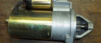
The ECU mass is usually arranged like this. Separate ground wires are removed from the ECU connector and connected to the engine via the starter mounting bolt. Ground wires are usually black
Everything is simple and reliable. But in reality, over time, the voltage begins to drop in this section of the circuit, slowly but surely, disrupting the operation of the system.
Therefore, this unit must be periodically checked and maintained. We will look at how to do this further.
Types of ECU VAZ 2114
On-board computer VAZ 2114 operating instructions
The car was produced for more than 10 years, constantly improved, the characteristics became better and better. Of course, this was achieved through the use of new motors, sensors, and actuators. And most importantly, thanks to the installation of control units, whose operating speed is much higher (you have all heard about the frequency of processors; it is on this parameter that the characteristics of internal combustion engines depend today).
January-4 and GM-09
Until 2003, these electronic units were installed. They had a very wide range of models, the main difference between them was the presence or absence of a resonant-type knock sensor. The price of a VAZ 2114 ECU of the “January-4” type is no more than 6,000 rubles. The list of modifications is given in the table:
Weight between engine and body
Line “31”, popularly called “ground”, “minus” or “negative circuit”, is very important for a car. And not only for electrical equipment, but also for many other systems, including the engine or automatic transmission.
Almost all cars have a single-wire on-board network system and the role of the “minus” in this circuit is played by the metal parts of the body. This greatly reduces the number of wires and reduces the cost of the car.
It turns out that all participants in this chain have their own connection to the body - instrument panel, headlights, ECU, engine, etc.
Despite the visual integrity of these connections, over time, due to oxidation and corrosion, the contact slowly and imperceptibly deteriorates, which leads to voltage drops when powerful consumers are turned on or disruption of the system.
I would divide the mass connections into main and local. Let's say that the connection of the head light masses is local and if this connection is disrupted, only the head light will suffer. But if the ground contact from the battery to the body is broken, the entire on-board network will suffer, and this may cause problems in the operation of the engine and other important components and assemblies.
Troubleshooting
For uninterrupted operation of the battery, the system must be equipped with good quality wires; in this case, copper wires are the most suitable, since they have the best characteristics when operating under voltage.
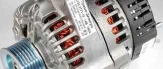
The thin positive wire coming from the generator must be replaced with a thicker wire.
To protect the existing mass and ensure longer and more trouble-free operation, it is necessary to treat all existing connections and terminal contacts with a special lubricant that has an anti-oxidation function.
You can strengthen the mass by placing additional mass near the generator. Of course, you should not use a thin negative wire to connect to the car body; it is better to use a thick wire. The result will be better, and if problems arise with the main wire, the additional one will be able to start the car, and again you will not have to listen to the clicking of the relay.
As a result of the procedures performed, the car will start more confidently. We will eliminate the problem of frequent battery discharge, which will avoid the loss of much-needed volts for the car and, as a result, ensure the most stable and sufficiently high voltage coming from the generator.
Where is the mass located: engine - battery - body
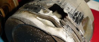
On most cars, the engine-body mass has a primitive appearance and is made of two pieces of cable connected together by crimping on the negative terminal of the battery
This crimp connects two wires. One goes to the engine and is secured with the starter mounting nut...
...and the second one on the body in the area of the left wing
It would seem that this is the simplest and most reliable chain that will serve well for years. But this is not at all true and it’s all to blame for the weak points in this design, which do not withstand the test of atmospheric influences.
Bad mass inexhaustible source of glitches
Lada 2106 new life Logbook Ground wire from battery body
Attention! This technique is applicable only to the 2110 and 2113-2115 “new” models, in the sample the fan control is carried out according to the mass family. In wire 2108-2115 of the 'old' type, the fan can be controlled by switching +12V
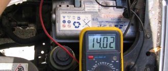
VAZ: Car Patient 21114, manufactured in 2005, mileage Complaint km., 8V, 1.6L.
7500: On a warm engine, the TPS position is 1-Perceptible at idle. 2%% (100-200 rpm) radiator. Independent of the instance sensor (Domestic or GM). The test revealed a change in the voltage at the TPS output from 0.41 to 0, when the electric radiator fan was turned on at 57V. text in Further in the fork of measured voltages, the value of the hyphen is on the left when the radiator is turned off, and on the right when the electric fan is on. Measurements were carried out using a digital tester manufactured by Mastech
insufficient: Diagnosis of reliable ground contact between the ECM and the vehicle ground, known as a “bad ground”.
Additional: Treatment with thick wire in double insulation, 3x2 cross-section, 5 sq. mm. additional mass was laid from the negative battery terminal to the metal frame of the center console of the instrument panel. The terminals at both ends of the additional wires are crimped and soldered. On the frame, the wire is secured to the ECM ground wire stud, together with its standard ground wires. Also soldered to the standard terminals is the ground wire installed between the battery minus and the car body.
The wire is screwed into place. Result: The voltage at the TPS output began to change within 0.39-0.46V. Next, the wire goes to the ground on the radiator fan relay, the harness is cut off from the ECM and connected to the metal frame with a separate wire. The extension of the wire is carried out using the transition method of crimping a tinned copper tube. Result: 0.37-0, Related!!!!!!!! 39V measurements: The voltage on the green, mass TPS wire before reconnection is 0.056-0.215V. After 03V 0.03-0, reconnection! Those. practically does not change! In addition, there is a tendency to reduce the voltage at the output of the TPS closed when the throttle valve is closed as the controller improves the contact between the ECM and the vehicle ground. Conclusion: the assurances of all OJSC AVTOVAZ about improving the quality of electrical connections in the cars they produce are not worth a penny. In most cases, it is possible to achieve engine operation under the control of January I 7.9.7 and ECM 7.2 only by making additional changes to the operation of the vehicle's electrical circuit that are not accepted by the manufacturer as a warranty. PS. Such a thick cross-section of wire was taken because there were no other wires with a similar cross-section at hand, and it was simply too lazy to cut individual wires into its own. In fact, perhaps 2.5 squares would be enough.
Text and Skrydlov: I.N. photo, Lyubertsy (aka Aktuator) chiptuner.ru
How to check mass on a car
In fact, only a small group of motorists pay enough attention to this issue. Others begin to think about it when, when the cooling fan or headlights are turned on, the engine speed begins to sag, or when the rear window heating is turned on, the engine begins to tremble, transmitting vibration throughout the body.
But even at this stage, many limit themselves to a banal inspection and tightening the ground connection nuts on the engine and body. Everything is screwed down - that means everything is in order.
Then the car begins to jerk for no apparent reason, idle speed freezes, misfires, security system glitches, and so on, until the starter fails at the most inopportune moment. But even here, many will not go check the masses, but will run to the store for a new starter. After all, the wire to the starter is intact and there is voltage, but it, a radish, does not turn.
Replacing the starter, of course, does not help. As a result, the still-living battery goes into recycling and the situation seems to have improved, but after a couple of days the starter fails again and you begin to believe in brownies and otherworldly forces that have nothing better to do than cause damage to someone else’s car.
But, fortunately, reason wins and the advice of a good man is remembered - to check the masses.
Again, what's so difficult about this? It is necessary to check the resistance from the engine to the body.
Once again about the “Masses”
©Oleg Bratkov, Pyatigorsk
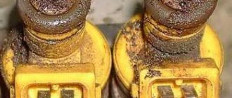
Controllers January 7. 2 and Bosch 7. 9 . 7 have in their 81-pin connector separate leads for the sensor masses, which reduces the dependence of the sensor readings on each other, increases the measurement accuracy and is apparently necessary to comply with Euro-4 standards. However, some smart guy at the wiring harness manufacturing plant, with a light hand, combined all the masses of the sensors with one crimp. Controllers January 5. 1, Bosch 1. 5 . 4 actually worked like that, all the masses of the sensors came to one terminal. The difference is small. However, the “naughty” idea of the designers went further. Here is a photo of the electrical wiring of a VAZ 2115. Next to the controller connector there are two wire crimps. The one on the right is a mass of sensors, screens... It would be better if each wire went to its own terminal, but let it remain that way. The crimp on the left (vinyl chloride tubes and electrical tape have already been removed) is the power mass. What is the main mistake of domestic manufacturers? This is the wire that connects these crimps. Marked with yellow dots, the wire itself is just brown. You just need to cut it out, solder the crimps (they took it apart in vain, or what?), and wrap it with electrical tape, that is, restore the insulation.
The essence of the modification is that the masses of sensors should come only to the controller. That is, if you remove the connector from the controller, neither the DT, nor the DPS, nor the mass air flow sensor, nor the DD on the body (minus AB) “rings”. It is necessary to remove the connector from the controller and, for example, the diesel engine, and check the resistance between the engine and the ground wire in the connector. We connect both wires to the engine. Both must have high or infinite resistance - an open circuit. If there is a short circuit, remove the electrical tape next to the controller, look for the specified jumper and remove it. After this, the masses of the sensors will be connected to the machine body only with the controller connector on!
All wires have resistance, even very thick ones. Let's remember Uncle Ohm's law. The greater the resistance and the greater the current, the greater the voltage. The mass wires obey the same law. Physics though. When the relay, injectors, IAC are turned on (the ignition keys have a separate thick ground wire and are not involved in our process), the voltage on the ground of the controller itself changes relative to the mass of the car.
Apparently the injectors and IAC operate constantly and their intervention is not taken into account. However, current flows through the fan relay - it does not flow for a relatively long time. When the fan relay is turned on, the voltage at the ground of the controller is even higher than at the point where the ground wire connects to the body, and if you move along the ground wire, it gradually decreases. There is always a potential difference, it’s just sometimes greater, sometimes smaller.
With proper wiring of the ground wires, the voltage on the common wire of the sensors does not change relative to the ground of the controller itself and is practically equal to zero. At the very least, due to the lower sensor currents, the voltage fluctuations are much smaller. A change in voltage on the controller ground relative to the car body or battery negative leads to the same change in voltage on the sensor ground and does not affect their readings. And indeed, on all cars where there is a smell of electronics, for example, on a carburetor eight with electronic ignition, where the Hall sensor is located in the distributor, three wires go to the sensor. Power, signal and ground from a separate terminal of the ignition switch.
But let's return to our ram. A jumper added at the factory connects the mass of the sensors to the wire running from the controller to the machine body, on which the voltage changes due to a change in current, in particular, when the fan relay is turned on. As a result of turning on the fan relay, the voltage on the controller ground becomes higher. But, as we remember, it gradually decreases as we move along the wire. The point on the power ground where the ill-fated jumper is connected can be considered “zero”, since the remaining wire between the crimp and the car body is not involved in creating interference.
And then everything is simple. The mass of the sensors is connected to “zero”. From this “zero” to the mass of the controller itself, the resistance of the power wire is included. The relay turned on - the voltage on the controller ground became greater than it was. The ADC reference voltage also increased relative to “zero” accordingly. However, the mass of sensors remained in place, at “zero,” and the controller, having processed the ADC readings, will “see” a decrease in the voltage from the sensors. Well, mass air flow sensor, diesel engine... well, it’s decreased, it doesn’t happen to anyone... What a range there! However, for the TPS, reducing the voltage of the closed state will be reduced to storing this very “closed state voltage” in the controller’s RAM, that is, the minimum voltage from the TPS. Here we are