The ignition timing is checked and set at engine idle (at a crankshaft speed of 820–900 rpm). The angle should be within 0±1° BTDC. If the ignition timing is incorrectly set, the engine overheats, does not develop full power, consumes excess fuel, and detonation occurs.
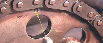
The ignition timing is checked by the mark on the flywheel and the scale in the clutch housing hatch (the rubber plug is removed). When combining the marks on the flywheel with the middle division (notch) on the scale, the pistons of the 1st and 4th cylinders are installed at TDC. One division on the scale corresponds to 1° of crankshaft rotation.
The moment of ignition of the air-fuel mixture in the combustion chamber is the moment of formation of a spark between the electrodes of the spark plug. Setting the ignition timing is the possibility of igniting the mixture at a certain position of the piston relative to TDC. The characteristics of automatic ignition timing regulators are shown in Fig.
1 Since it is easier to navigate by the crankshaft (pulley, flywheel), ignition before TDC (advance), at TDC and beyond TDC (lag) is usually assessed in angular degrees along the crankshaft with the sign V or (Fig. 2). The scale can be in the hatch of the clutch card or on the pulley (Fig. 2).
In the first case, there is a risk (TDC mark in the corresponding cylinders) on the flywheel, and in the second there is a pin in the timing cover (scale on the pulley). Due to the smaller diameter of the pulley compared to the flywheel, the scale can cover the entire range of changes in the ignition timing angle. Whatever vehicle the ignition is installed on, you need to start by checking the three compliances. At the moment of ignition, the following must be in the appropriate (definite) position relative to each other: the crankshaft, camshafts and distributor shaft.
The main reference point (almost always) is TDC in the first cylinder. On a 4-stroke engine, the working cycle is carried out in two revolutions of the crankshaft or in four strokes of the piston (a half-turn stroke, one piston stroke), so the piston of the first cylinder will be at TDC twice per cycle. Once between the exhaust and intake strokes, the other between the compression and expansion strokes (power stroke). It is the last TDC that interests us. For mutual orientation of the crankshaft and camshaft, various marks are used: protrusions, pins, pressed balls, marks, grooves, holes, etc.
D. The position of the distributor roller is controlled by the location of the outer contact of the rotor relative to the side electrode of the first cylinder. (KSZ, BTSZ). Let's pay attention to the marks on the crankshaft pulley and the camshaft drive cover (Fig.
3). Mark 4 (protrusion, boss) on the pulley is used when there is access to the front of the engine (the radiator or engine has been removed). When setting the ignition timing under normal conditions, mark 4 (cut) is used on the pulley edge on the engine side. The combination of marks 4 and 3 (Fig. 3) only indicates that the pistons of the first and fourth cylinders are at TDC. You can find out which cylinder has the end of the compression stroke by looking at the outer contact of the rotor, after first removing the distributor cap.
If the distributor is removed, proceed as follows. Having plugged the spark plug hole of the first cylinder with a paper plug, we manually turn the crankshaft. The moment the plug comes out indicates the TDC of the piston of the first cylinder at the end of the compression stroke. In cases where routine maintenance of the engine with valve adjustment is carried out, they act differently. With the cylinder head cover removed, the bottom marks 4 and 3 coincide (Fig.
3) and upper 1 and 2 (Fig. 4) indicates that the end of the compression stroke is in the fourth cylinder. With the head cover removed, the presence of three correspondences on the Zhiguli is best checked by TDC of the fourth cylinder.
Usually it is written that if the upper marks match (Fig. 4), the lower marks 4 and 3 must also match (Fig. 3). In reality, even on new cars, such a coincidence does not happen.
Determination of early or late ignition
The stability of the engine, its power, fuel efficiency, etc. directly depend on the correct settings and uninterrupted operation of the ignition system.
Normally, on four-stroke engines, the fuel-air mixture should ignite at the end of the compression stroke, that is, just before the piston rises to top dead center. This ignition timing is due to the fact that the mixture requires a certain time to burn, after which the energy of the expanding gases pushes the piston down and the power stroke begins. By late or early ignition we mean a delay or advance in the operation of the ignition system in relation to the position of the piston in the cylinder. In other words, a spark from the spark plug is formed and ignites the fuel-air mixture not at the optimal moment when the piston approaches TDC, but earlier or later than this moment. This phenomenon is called early or late ignition. For this reason, owners of vehicles that have the ability to independently adjust the ignition timing (ignition timing) are often faced with the need to adjust the ignition.
When is it necessary to set the ignition by marks?
Setting the ignition by marks is necessary when replacing:
In addition, the ignition is checked and adjusted if problems arise with the timely ignition of the mixture. Most often, such problems are caused by the timing belt stretching or “licking” its teeth. If the belt “jumps” even one tooth relative to the mark, the engine will operate in emergency mode.
Ignition system VAZ 2110, 2111, 2112 (ten)
VAZ 2110, 2111, 2112
repair manual
Electrical equipment Fuses and relays Replacing the fuse box Generator (device, characteristics) Generator malfunctions Replacing the generator belt Replacing the generator Disassembling and repairing the generator Starter (device, characteristics) Starter malfunctions Replacing the starter Disassembling and repairing the starter Checking and replacing the ignition switch Disassembling and repairing the ignition switch Replacement of spark plugs ignition ECM Diagnostics of the ECM and fault codes ECU (controller) - description Replacement of the ECU (controller) Replacement of the coolant temperature sensor Replacement of the knock sensor Replacement of the mass air flow sensor Replacement of the CO potentiometer Replacement of the speed sensor Throttle position sensor Replacement of the idle speed control Replacement of the crankshaft position sensor Replacement of the Lambda probe Replacement of the phase sensor Replacement of the ignition module Ignition system Ignition malfunctions Setting the ignition timing Replacement of the ignition distributor Checking the operation of the hall sensor Repair of the ignition distributor Checking and replacing the ignition coil Adjusting the headlights Replacement of the headlight Replacement of the rear light Replacement of the light on the trunk lid Removing the interior lamp Replacement headlight corrector Removing the steering column switches Replacing the horn Replacing the windshield wiper Malfunctions of the windshield wiper Repairing the windshield wiper motor Replacing the windshield washer reservoir Replacing the windshield washer pump Replacing the windshield washer fluid sensor Rear wiper (mod. 2111, 2112) Replacing the radiator fan motor Operation of the heater motor (principle, diagram) Replacing the heater motor Disassembling and repairing the heater motor Replacing the additional resistor of the heater Replacing the air temperature sensor Rear window heater Replacing the cigarette lighter and its backlight Instrument cluster (description, diagram) Malfunctions of the instrument cluster Removing the instrument cluster Replacing the instrument cluster lamps Disassembling the instrument cluster Checking the operation of the carburetor solenoid valve unit Malfunctions of the EPHH unit
How to understand that the ignition is late or early
Ignition of the working mixture of fuel and air in the cylinders with advance or delay leads to certain malfunctions in the operation of the engine. The list of main signs by which you can identify an incorrectly installed ignition includes:
- difficulty starting the engine;
- noticeable increase in fuel consumption;
- the engine loses throttle response, power drops;
- unstable operation in idle mode is noted;
- responsiveness to pressing the gas pedal disappears;
- engine overheating and detonation occur;
An incorrect ignition angle can manifest itself in the form of characteristic pops that are heard in the exhaust system, carburetor, etc. It is quite obvious that further operation of an internal combustion engine with a broken ignition timing can lead to more serious engine damage, especially if persistent detonation occurs.
Consequences of an incorrectly set ignition angle
Both late and early ignition negatively affects the operation and service life of the engine. It should be added that not only power and fuel consumption depend on the correct ignition timing. If a spark on the spark plug forms earlier than expected, then the pressure of the expanding gases begins to counteract the piston rising to TDC (pre-ignition). Ignition of the working mixture after the piston has begun to move down from TDC leads to the fact that the released fuel energy “catches up” with the piston and enters the exhaust, rather than doing useful work (late ignition).
Signs of early ignition appear in the form of the following symptoms:
- the appearance of a metallic ringing sound during engine operation, which is localized in the area of the cylinder block;
- idle speed fluctuates, the engine is unstable;
- after pressing the “gas” there is a pause, the engine does not “pull” and overuses fuel;
Late ignition also causes significant damage to the engine. In this case, combustion of the mixture occurs under conditions of decreased pressure and increased volume in the internal combustion engine cylinder. The combustion process of the fuel-air mixture itself is disrupted, which burns out during the working stroke of the piston. As a result, signs of late ignition are:
- the engine loses power, you need to press hard on the gas to accelerate;
- there is a significant increase in fuel consumption;
- the engine is heavily coked by deposits and carbon deposits;
- improper combustion of the mixture leads to engine overheating;
Replacement of distributor for VAZ 2110, VAZ 2111, VAZ 2112
Welcome! The distributor is the thing that makes the engine work on carburetor cars (the injector uses a crankshaft sensor instead, and on diesel engines there is no ignition system at all, because the fuel in them ignites itself), the real name of the distributor is “Ignition distributor”, from the word distribute, twist, it is he who controls the moment at which it is necessary to give a spark to a certain spark plug (As you know, there are only four spark plugs), but the name distributor came from the people and it stuck on it forever.
Note! To replace this part: You will need a screwdriver and a small set of wrenches, the approximate replacement time is 10-15 minutes and most importantly, set the marks with chalk or a marker, you will have to drive without them and adjust the ignition (Although after installing a new distributor, the ignition is still We recommend that you go and adjust it, or if you have a strobe light, then you don’t need to go anywhere; we’ll explain to you how to adjust it using this device)!
Summary:
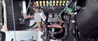
Where is the distributor located? Open the hood and as soon as you open it, look in the right corner (As the car moves, it turns out to be from you to the left), in the corner where the battery is still located you will find this unit, five more thick high-voltage wires will be connected to its cover, in more detail it is indicated by an arrow in the photo below:
Setting the ignition timing yourself
Correctly set ignition timing requires adjustment of the OZ. It is necessary to adjust the ignition angle at idle speed. It should be taken into account that the optimal idle speed is considered to be in the range of 850-900 rpm. The ignition timing angle is also within a certain range from -1 (negative) to +1 (positive) degrees. The degree indicated is the degree relative to TDC.
The specified lamp is connected to the positive terminal on the ignition distributor, and is also connected to ground. Next, we will look at the main available methods for setting the ignition using the following example of a domestic “classic”:
Setting up strobe ignition
- the engine must be warmed up until it reaches operating temperature;
- The strobe light is connected to the on-board network;
- unscrew the fixing nut of the ignition distributor-interrupter cover;
- the alarm signal sensor is placed on the high-voltage wire of the first cylinder;
- if there is a vacuum corrector hose, you will need to remove and plug the specified hose;
- the strobe light is directed to the crankshaft pulley;
- the engine starts and idles;
- the distributor body is rotated;
- the position of the breaker-distributor body is fixed so that the pulley mark coincides with the corresponding mark on the timing belt;
- after aligning the marks, the fixing nut is tightened;
Setting the OZ according to the control light
If you use the light bulb ignition method, then you need to turn the engine crankshaft so that the mark on the crankshaft pulley matches the mark on the timing cover. In this case, the slider on the ignition distributor should point to the spark plug wire of the first cylinder.
Next, the distributor lock nut is loosened, after which one wire from the light bulb is connected to the wire that goes to the ignition coil from the distributor. The second wire from the lamp is installed to ground. Then you need to turn on the ignition and rotate the distributor body clockwise until the control lamp stops lighting. After this, you should carefully turn the distributor body back, that is, counterclockwise. Having determined the position at which the light bulb lights up, it is necessary to fix the distributor body in this position. Fixation is done by tightening the distributor nut.
Assembly and installation of distributor VAZ 2110
We assemble the ignition distributor of the VAZ 2110 in the reverse order, lubricating the edge of the oil seal and the bearings: Before installing the distributor sensor, put on the slider, but do not close the cover (or remove the cover if we are installing a new distributor sensor), lubricate the rubber ring with engine oil, and put on the distributor sensor onto the studs and, turning the shaft by the slider, we achieve alignment of the camshaft slot with the coupling. For the convenience of adjusting the ignition timing of the VAZ 2110, there are divisions and “+” and “–” signs on the flange of the ignition sensor-distributor, and on the body of the auxiliary units there is an adjusting protrusion. One division on the flange corresponds to eight degrees of crankshaft rotation
We align the protrusion on the body of the auxiliary units with the middle of the scale on the sensor-distributor, tighten the nuts. Using a strobe light, we check and set the ignition timing of the VAZ 2110. To do this, connect the “+” clamp of the strobe light to the “+” terminal of the battery, the “ground” clamp to the “-” terminal of the battery, and connect the strobe sensor clamp to the high voltage wire 1- th cylinder. To check the set ignition, start the engine and direct a flashing stream of strobe light into the clutch housing hatch. If the ignition timing is set correctly, then when the warm engine is idling, the mark on the flywheel should be opposite the slot in the clutch housing shield.
To correctly set the ignition timing of the VAZ 2110, stop the engine, loosen the nuts securing the ignition distributor sensor and turn it to the required angle. To increase the ignition timing angle, turn the sensor-distributor housing clockwise, and to decrease it, turn it counterclockwise. Tighten the distributor mounting nuts. This completes the replacement of faulty parts in the VAZ 2110 distributor and its replacement or installation.
Source
Other methods of setting up and checking the ignition on a car
You can also set the ignition to spark or independently select the angle when the engine will operate most stably and smoothly. The simplest and least accurate method is to install based on the operation of the motor. To set up, start the engine, after which the nut securing the distributor housing is loosened. Next, you will need to turn the distributor housing clockwise and counterclockwise, finding the position at which the engine runs smoothly and the XX speed is the highest. After this, you should turn the breaker body a couple of degrees clockwise and tighten the distributor nut.
Then the wire contact should be placed near ground (distance about 5 mm) and turn on the ignition. After this, the breaker body should be rotated 20 degrees clockwise. Now the housing needs to be rotated back until a spark appears between the ground and the wire contact. In this position, the distributor body must be secured with the breaker fastening nut.
Upon completion, it is necessary to check the correctness of the OZ in motion. With a warm engine, the car should be accelerated to 40-45 km/h, after which fourth gear is engaged and the gas pedal is fully pressed. Next, it is necessary to assess the degree of detonation. It is considered normal when, immediately after engaging 4th gear, detonation is briefly present (2-3 seconds), but disappears as the car accelerates. If detonation continues after acceleration, then the likelihood of pre-ignition is high. If there is no detonation when the 4th gear is engaged, then the ignition is delayed. In such cases, the SOP adjustment should be repeated to obtain an optimal result.
Installing the ignition on a VAZ (“classic”)
They are equipped with one of two types of ignition. The first is contact: here the opening is carried out by turning the distributor shaft (mechanical method). The second type of ignition is electronic, non-contact: it uses a Hall sensor, which determines the time of spark formation.
How the ignition system works
When the piston reaches the TDC position, it compresses the combustible mixture with maximum force. At this time, a high voltage is formed in the coil. From the distributor cover it is supplied through high-voltage wires to the spark plugs, where a spark is formed that ignites the mixture. When the crankshaft speed increases, the ignition timing changes. This procedure is “carried out” by a vacuum regulator (attached to the ignition distributor), connected via a tube to the intake manifold. As a result, optimal power is achieved in any engine operating mode.
Symptoms of a problem
- the engine cannot be started or it runs extremely unstable (stalls);
- deterioration in driving dynamics: sluggish acceleration;
- increased fuel consumption;
- pops in the muffler;
- vibration during operation of the power plant.
How to set the ignition timing with a strobe light
This is a fairly accurate method that does not require dismantling the valve covers and distributor. The procedure takes literally a few minutes and consists of the following steps:
- with the engine turned off, loosen the nut securing the ignition distributor (key 13), noticing its original position;
- clean the front motor cover (under the pulley) from dirt so that the marks are visible (one long, two shorter);
- Connect the negative terminal of the strobe to the engine ground, the positive terminal to the ignition coil (terminal or nut on the side), fix a separate clamp on the high voltage wire of the 1st cylinder.
- start the engine and point the strobe light at the pulley;
- the mark on it should coincide with the central tide on the front cover of the BC if A80 gasoline is used, and with the longest outer one if the fuel is AI92;
- if this is not the case, smoothly turn the distributor until a match occurs.
How to set the ignition timing on the injector yourself
Long gone are the days when the world's first car rolled off the assembly line. It was equipped with a new injection system. The production of these machines today has increased 10-20 times. As you understand, we are talking about cars with injection systems. Let's find out how to set the ignition timing on the injector.
Today, 80 percent of people become owners of just such cars. Therefore, the ability to configure the ignition system is regarded as a very important advantage. It will allow you to always stay on the move, saving money on repair services and fuel.
How the ignition system works and how it works
The VAZ 2110 abandoned such familiar ignition elements as a coil and a distributor. So, a special ignition module is used here, which consists of high-energy control electronics, as well as a pair of coils. It is important to note that such a system does not require frequent maintenance, because There are no moving parts here. The VAZ 2110 ignition system also does not require special adjustments, because For this purpose, a controller is installed here. He carries out all the settings and adjustments.
The ignition system is based on the “idle spark” method. This is a special method of spark distribution. As you know, cylinders in a car engine work in pairs (1st cylinder with 4th, and 2nd with 3rd). So, a spark fires in two cylinders at once: a working spark in the cylinder where the compression stroke of the mixture occurs, and an idle spark in the one where the exhaust stroke occurs. Because the current in the windings of the system coils is constant, it turns out that on the first spark plug the electrons move from the central electrode to the side electrode, and on the second - vice versa (from the side to the central).
Depending on the type of engine, the VAZ 2110 can use two types of spark plugs. Thus, for 8-valve engines, spark plugs of the A17DVRM type are used, and for 16-valve engines - AU17DVRM (here the wrench size is reduced to 16 mm). At the same time, the distance between the electrodes of the spark plugs is only about 1.0–1.15 mm.
As we noted above, an element such as a controller is responsible for ignition control. To most accurately control the system, the controller analyzes the following information:
- coolant temperature;
- current position and speed of the crankshaft;
- presence of detonation;
The crankshaft position is analyzed using a special sensor that transmits information to the controller.
Only after this is the firing sequence of the ignition module coils calculated. At first glance, the system is quite complex. But in operation everything is very simple. In addition, maintenance and repair of the ignition system of the VAZ 2110 and other models does not take much time.
Almost half a century has passed since the first time a car equipped with a gasoline injection system rolled off the production line. Currently, the production of such machines has increased tenfold compared to carburetor models.
A person who is going to buy a modern car will most likely become the owner of a car with an injection-type gasoline engine. That is why the ability to configure the ignition on an injector is useful to many motorists.
Tools and Diagnostics
ATTENTION! A completely simple way to reduce fuel consumption has been found! Don't believe me? An auto mechanic with 15 years of experience also didn’t believe it until he tried it. And now he saves 35,000 rubles a year on gasoline! Read more"
Tools are an important part of any job. They will be needed to make adjustments to the process of issuing SOP. Mandatory tools include screwdrivers, a measuring instrument, wrenches, and preferably a laptop with a specially installed program designed for diagnosing injection-type power units.
First, you should know that on an injection engine, electronics are responsible for driving the car. It is subordinate to the head – the computer system. Conducting quality testing of all components of the injection system is the first thing to do.
Here's how it's done:
- the ignition is turned on;
- the supply of fuel by the electric fuel pump is checked (the characteristic sounds of activation of the pump performing the injection should be heard).
If there are no sounds of the fuel pump operating, you need to check the relay that controls the operation of the pump.
You should also pay attention to the instrument panel, on which the indicator may indicate. If this is the case, then you need to connect a laptop with a special program to the BC system. It will help you analyze errors and display them in a list.
If no problems are identified at this stage, then it’s time to start the internal combustion engine. On a functioning engine, the throttle assembly is checked first.
Here's how it's done:
- first, an external inspection of the sensor, which is responsible for the position of the damper, is carried out;
- then the wiring condition is tested;
- if everything is in order, it would not be superfluous to measure the voltage of the entire circuit and sensor using a measuring device;
- the obtained values must be compared with the standard indicators specified in the vehicle repair manual.
A normal current value can be considered to be in the range of 0.45-0.55V. The current value should not exceed 12 V, and the throttle opening degree should not be more than 1%. If deviations are noticed, then you need to adjust the throttle drive so that it closes the damper entirely.
Next, you need to press the gas pedal all the way, re-measuring the indicators this way. The damper open level should be 90%. As for the sensor voltage, the voltage must be 4.5 V.
Throttle actuator tuning is considered an important part of the work included in the diagnosis. It allows you to simultaneously set up a node and check the consistency of the values.
In order to adjust the drive you need to:
- disable the RDPV (sensor responsible for additional air flows);
- half open the throttle;
- make adjustments so that the damper completely covers the hole.
Lada 2113 Black Storm › Logbook › Instructions for flashing VAZ firmware for beginners, setting up UOZ
Stage 6. Creating combat firmware for driving around the city, setting up the ignition (UZ)
Warm greetings to everyone!
Today we will light, light, set on fire! I will try, together with you, to figure out the third main question of any firmware for a gasoline engine - when to ignite the fuel-air mixture?!
First, a little theory. What is UOZ? Translated as ignition timing. What kind of corner is this? How is it related to ignition? Where did the word advance come from? I’ll tell you in simple terms how I understand it!
For a full working cycle, 4 strokes occur in the engine: - Compression of the fuel-air mixture; — Working stroke; - Release; — Inlet; Now, as I understand it, this is a matter of degrees, which the firmware uses: - 0g - the piston is at TDC, the end of the compression stroke, the mixture is set on fire; — 180g — piston at BDC, end of stroke, start of release; — 360gr — piston at TDC, end of exhaust stroke, beginning of intake; — 540gr — piston at BDC, at the end of the intake stroke, the beginning of the compression stroke; - 720g - piston TDC, at the end of the compression stroke, and set the mixture on fire again.
In total, the crankshaft rotates two revolutions - 720 degrees. We are interested in the moment - the end of the compression stroke - 540 - 0 g! It is at this moment, when the engine has compressed the fuel mixture very strongly, that it is necessary to ignite it in order to obtain maximum pressure on the piston. The stronger the pressure on the piston, the more powerful our motor. The pressure is maximum at the moment when all the fuel burns, the gases expand greatly, and it is at this moment that our piston must be at the very top of the combustion chamber - TDC (top dead center), so that powerful pressure begins to push it back down - to BDC (bottom dead center). dot). The stronger the pressure, the faster the piston moves down, the more powerful our motor. And we feel it with our body. And we say: “Waaaaaaaaaaaaaaaaaaaaaaaaaaaaaaaaaaaaaaaaaaaaaaaaaaaaaaaaaaaaaaaaaaaaaaaaaaaaaaaaaaaaaaaaaaaaaaaaaaaaaaaaaaaaaaaaaaaaaaaaaaaaaaaaaaaaaaaaaaaaaaaaaaaaaaaaaaaaaaaaaaaaaaaaaaaaaaaaaaaaaaaaaa majority time! Chip tuners have a device called an ass meter
.
Butt meter
- a device located inside a person that cannot be deceived; it shows the person how his car rolls. A very important device that replaces expensive dynos.
We laughed a little! The ignition timing is the angle before TDC is reached on the compression stroke. For example, OZ = 30g. This means that our spark plug will ignite the fuel-air mixture when the crankshaft is in the 0°-30° position, or 720°–30°. The calculation is simple: 720g - 30g = 690g.
But you ask, how is this possible? Why so early? The piston is not yet at the very top of the combustion chamber! I will now reveal the meaning of the word “advanced”. The fact is that while the mixture begins to burn, flare up, precious time passes! During this time, the crankshaft has time to rotate at a certain angle, it can have time to travel 20 degrees, it can travel 15 degrees while the mixture is burning. Thus, the piston manages to get closer to TDC.
In my opinion, the most difficult task of an engine tuner is to determine the best, most accurate ignition timing angle at which the fuel will have time to ignite by the time our piston is at TDC! This is the angle that gives a significant increase in power, it gives maximum acceleration.
Moreover, the burning time of the mixture is different, depending on the octane number of gasoline, the fuel-air ratio, the amount of this mixture in the combustion chamber, and the temperature of the fuel mixture. If the mixture is rich, it burns faster than a lean mixture. High octane fuel burns longer than low octane fuel. 98 gasoline burns longer than 95 gasoline.
Also, if you set the ignition angle very early, you can run into something called detonation. Detonation
- This is an explosion of the fuel-air mixture. The usual combustion speed of the mixture in a cylinder is hundreds of times less than the speed of explosion of the fuel mixture. Can you imagine what could happen to the engine if severe detonation begins? At best, nothing, at worst, you will have to collect the remains of the pistons and connecting rods from the pallet. Maybe the pan will tear off or the head will come off. I don’t wish this kind of grief on anyone.
So, it is important to know which angle is early
, and which one is
later
, so as not to get into detonation. Let's look at an example. Given an angle equal to 30 degrees and an angle equal to 35 degrees. Here the angle of 35 degrees will be before the angle of 30 degrees. (720-30=690g or 720-35=685g). 685g will come earlier than 690g. It's simple.
I noted several possible causes of detonation: 1) Low-quality gasoline with a low octane number. 2) High engine compression ratio. 3) Engine temperature (the higher it is, the higher the likelihood of detonation). 4) Ignition angle too early. 5) The mixture is too lean (15.5/1-16.5/1) (firstly, it burns worse, and secondly, it does not cool the combustion chamber).
Ignition: late and early
Which ignition is better? An experienced motorist or expert will immediately say: optimal. And in itself, late or earlier ignition is already extreme, capable of giving the car owner a lot of headaches.
The stability of the operation of an injection engine directly depends on proper adjustment of the ignition system. This will help increase the power of the internal combustion engine, reduce fuel consumption, and improve efficiency.
Ideally, on a 4-stroke internal combustion engine, the fuel assembly should ignite at the end of the compression stroke. This means that the fuel must ignite at the very moment when the piston reaches TDC. This process is due to the nuance that the fuel assembly needs a specific time to burn, after which the resulting force will push the piston down.
So, late or early ignition implies a delay or advance in the operation of the above process. In other words, the ignition system is configured so that a spark is formed and ignites the fuel assembly not at the optimal moment for this. This happens sooner or later.
It is not difficult to determine if the ignition setting is not optimal. Engine malfunctions observed periodically are evidence of this. You can also study the main signs that determine an incorrectly set ignition.
- If there is unstable operation of the power unit in idling mode.
- Starting the internal combustion engine is clearly difficult.
- Fuel consumption has increased.
- The responsiveness of the accelerator pedal is not as impressive as before.
- The engine often overheats and detonation occurs.
- The power of the power unit decreases, it loses throttle response.
In addition, an incorrectly set OZ leads to popping noises that radiate into the intake system. Further operation of a vehicle with a crooked OZ is impractical and leads to more serious problems with the power unit. This is especially dangerous if detonation is noticeable.
| Symptoms and signs of pre-ignition | Symptoms and signs of late ignition |
| Excessive detonation (piston defect, destruction of connecting rods). | Loss of power. |
| A clearly audible knocking sound in the engine (increased wear). | Poor starting (which causes the battery to suffer). |
| Loss of power (especially noticeable at low speeds). | Increased fuel consumption. |
| Increased fuel consumption. | Engine overheating (may even seize). |
The difficulty of determining ignition on fuel-injected internal combustion engines is due to the fact that everything depends on the electronics. In this case, the problem must be solved not by mechanical intervention, but by configuring and programming the ECU.
It is noteworthy that on used cars, various errors accumulate in the ECU memory over time. The latter can lead to firmware failures and improper functioning of the engine and ignition systems. To identify and reset detected errors, you will need, as mentioned above, to use special software.
Possible malfunctions of the contactless ignition system. VAZ 2110 Lada
7.7.8. Possible malfunctions of the contactless ignition system. Their causes and solutions
| The ignition timing is checked by the mark on the flywheel and the scale in the clutch housing hatch (the rubber plug is removed). When combining the marks on the flywheel with the middle division (notch) on the scale, the pistons of the 1st and 4th cylinders are installed at TDC. One division on the scale corresponds to 1° of crankshaft rotation. | |
| EXECUTION ORDER | |
| Cause of malfunction | Remedy |
| Engine won't start | |
| The switch does not receive voltage pulses from the contactless sensor: | Do the following: |
| – a break in the wires between the ignition distributor sensor and the switch | – check the wires and their connections; replace damaged wires |
| – contactless sensor is faulty | – check the sensor using an adapter connector and a voltmeter; faulty sensor replace |
| No current pulses are supplied to the primary winding of the ignition coil: | Do the following: |
| – a break in the wires connecting the switch to the switch or to the ignition coil | – check the wires and their connections; replace damaged wires |
| – switch is faulty | – check the switch with an oscilloscope; replace faulty switch |
| – the ignition switch does not work | – check and replace the faulty contact part of the ignition switch |
| High voltage is not supplied to the spark plugs: | Do the following: |
| – the tips of the high voltage wires are loose or oxidized; they are not seated tightly in the sockets; the wires are heavily soiled or their insulation is damaged | – check and restore connections, clean or replace wires |
| – wear or damage to the contact carbon, its hanging in the cover of the ignition sensor-distributor | – check and, if necessary, replace the contact angle |
| – current leakage through cracks or burnouts in the cover or rotor of the ignition distributor, through carbon deposits or moisture on the inner surface of the cover | – check, clean the cover from moisture and carbon deposits, replace the cover and rotor if they have cracks |
| – burnout of the resistor in the rotor of the ignition sensor-distributor | – replace the resistor |
| – the ignition coil is damaged | – replace the ignition coil |
| The spark plug electrodes are oily or the gap between them is not normal | Clean the spark plugs and adjust the gap between the electrodes |
| Spark plugs are damaged (cracked insulator) | Replace the spark plugs with new ones |
| The order of connecting high voltage wires to the terminals of the ignition sensor-distributor cover is violated | Connect the wires in firing order 1–3–4–2 |
| Incorrect ignition timing setting | Check and adjust ignition timing |
| The engine runs rough or stalls at idle | |
| Engine ignition too early | Check and adjust ignition timing |
| Large gap between spark plug electrodes | Check and adjust the gap between the electrodes |
| The engine runs unevenly and unsteadily at high crankshaft speeds | |
| The springs of the weights of the ignition timing regulator in the ignition distributor sensor have weakened | Replace the springs, check the operation of the centrifugal regulator on the stand |
| Interruptions in engine operation in all modes | |
| The wires in the ignition system are damaged, the fastening of the wires is loose or their tips are oxidized | Check the wires and their connections. Replace damaged wires |
| Wear of electrodes or oiling of spark plugs, significant carbon deposits; cracks in spark plug insulator | Check the spark plugs, adjust the gap between the electrodes, replace damaged spark plugs |
| Wear or damage to the contact carbon in the ignition sensor-distributor cover | Replace the contact angle |
| Severe burning of the central contact of the ignition sensor-distributor rotor | Clean the center contact |
| Cracks, contamination or burns in the rotor or cover of the ignition distributor sensor | Check, replace rotor or cover |
| The switch is faulty - the shape of the pulses on the primary winding of the ignition coil does not correspond to the norm | Check the switch using an oscilloscope, replace the faulty switch |
| The engine does not develop full power and does not have sufficient throttle response | |
| Incorrect ignition timing setting | Check and adjust ignition timing |
| Sticking weights of the ignition timing regulator, weakening of the springs of the weights | Check and replace damaged parts |
| The switch is faulty - the shape of the pulses on the primary winding of the ignition coil does not correspond to the norm | Check the switch using an oscilloscope, replace the faulty switch |
↓ Comments ↓
1.0 General information 1.1. Vehicle Specifications
2.0 Engine 2.1 Possible engine malfunctions. 2.2 Replacing the coolant 2.3 Replacing the engine oil and oil filter 2.4. Installing the piston of the first cylinder to the TDC position of the compression stroke 2.5 Replacing the camshaft drive belt and tension roller 2.6 Adjusting the camshaft drive belt tension 2.7 Removing, troubleshooting and installing the flywheel 2.8. Replacing engine seal parts 2.9 Cylinder head 2.10 Grinding in valves 2.11 Adjusting clearances in valve drive 2.12 Removing and installing engine 2.13. Engine repair 2.14. Lubrication system 2.15. Cooling system 2.16. Exhaust gas system 2.18. Features of VAZ-2112 engine repair
3.0 Transmission 3.1. Clutch 3.2. Gearbox 3.3. Front wheel drives
4.0 Chassis 4.1. Checking the technical condition of suspension parts on the car 4.2. Rear suspension
5. Steering
5.0 Steering 5.1 Inspection and check of the steering on the vehicle 5.2. Steering column 5.4. Steering mechanism 5.5 Possible steering malfunctions.
6. Brake system
6.0 Brake system 6.1. Vacuum booster 6.2. Main brake cylinder 6.3. Pressure regulator 6.4. Brake hoses and tubes 6.5 Bleeding the brake system 6.6 Replacing brake fluid 6.7. Front wheel brakes 6.8. Braking mechanisms of the rear wheels 6.9. Parking brake 6.10 Possible malfunctions of the brake system.
7.0 Electrical equipment 7.1. Mounting block 7.2. Generator 7.3. Starter 7.4. Ignition switch (lock) 7.5. Checking and replacing spark plugs 7.6. Integrated engine management system (fuel injection system) 7.7. Contactless ignition system 7.8. Lighting, light and sound signaling 7.9. Windshield wiper 7.10 Replacing the electric motor of the radiator fan of the cooling system 7.11. Heater electric motor 7.12. Cigarette lighter 7.13. Instrument cluster 7.14 Checking the carburetor solenoid valve control unit 7.15 Possible malfunctions of the EPHH control unit. 7.16 Electrical diagram of a VAZ-21102 car 7.17 Electrical diagram of a car with a carburetor engine 2110 7.18 Engine control diagram 2111 (pin M1.5.4) 7.19 Engine control diagram 2111 (pin MP7.0) 7.20 Control diagram for engines 2111 and 2112 (pin M1) .5.4N, "January-5.1")
8.0 Body 8.1 Possible body malfunctions. 8.2. Replacing the buffers 8.3 Removing and installing the radiator trim 8.4 Removing and installing the locker 8.5 Removing and installing the wing 8.6. Hood 8.7 Removing and installing upholstery, trim and windshield frame lining 8.8. Trunk lid 8.9. Side doors 8.10 Removing and installing the front seat 8.11 Removing and installing the upper and lower lining of the floor tunnel 8.12. Seat belts 8.13. Rear view mirrors 8.14. Instrument panel 8.15. Heater 8.16 Anti-corrosion compounds for body treatment 8.17. Features of body repair of models 2111 and 2112 8.18. Body care
9.0 Appendices 9.1 Fuels, lubricants and operating fluids 9.2 Basic data for adjustments and control 9.3 Filling volumes 9.4 Lamps used in the car
Exhibiting UOZ on your own
The magnitude of the SOP depends directly on the amplitude of rotation of the crank shaft. The higher the rotation speed, the earlier the SOP should be set. Otherwise, there will be a decrease in power, overheating and premature failure of the internal combustion engine.
So, work begins with preparing the keys and indicator. Some experts also recommend acquiring a special OZ corrector, which allows you to set this characteristic automatically.
- The car should be put in neutral and the handbrake should be applied;
- remove the cover from the breaker;
- use a special wrench to turn the crank shaft until the marks on the cover and the shaft pulley match;
- connect the indicator at one end to the ignition module, at the other end to the ground of the power unit;
- loosen the breaker fastening;
- turn on the ignition;
- hold the distributor slider against the stroke and turn the breaker until the indicator goes out;
- turn the distributor a little more, and then return it to the original exposure and record it at the very moment the indicator lights up.
A VR or vacuum regulator is introduced into the system in order to automate the adjustment of the SOP as much as possible. The VR independently changes the angle, depending on a particular load.
For example, if the power unit operates in the XX mode, the VU regulator turns the distributor disk towards late ignition. And vice versa, as soon as the load increases, a vacuum occurs, the VR turns the distributor back.
In principle, on a modern fuel-injected car the system is automatically adjusted. However, situations are not uncommon when the factory settings are lost, and the OZ has to be set manually. But in any case, and any specialist will confirm this, you must first make sure that such adjustment is necessary.
Forget about fines from cameras! An absolutely legal new product - Traffic Police Camera Jammer, hides your license plates from the cameras that are installed in all cities. More details at the link.
- Absolutely legal (Article 12.2);
- Hides from photo and video recording;
- Suitable for all cars;
- Works through the cigarette lighter connector;
- Does not cause interference to radios and cell phones.
Video
Perhaps adjusting the gap on the spark plugs will help solve the problem:
Or setting ignition marks:
Why do you need to adjust the ignition timing on the VAZ-2110? Many motorists download software updates for the ECU from the Internet, but they themselves do not understand it at all. Is it any wonder that after such a re-flashing the car simply refuses to drive. Before downloading the update, you must check whether there is detonation.
If the ignition is set at 10°, then the spark plug will produce a spark after the crankshaft reaches ten degrees before TDC for a particular cylinder. And you need to ignite the mixture before TDC for the reason that it needs a certain time for it to burn correctly.
Our task is to ensure that the mixture is ignited at the moment when the piston is located in the upper part of the cylinder and it begins to forcefully move downwards. Now I will tell you about my personal experience. On the trip, I took a laptop with the OPenOLT program loaded, which I connected to the car’s diagnostic connector. I drove both around the city and on the highway, tried different driving modes. Then I launched the EcuEdit program, went to the Custom section and started doing everything according to the existing instructions. Find the line Fdet and press the “filter” button.
At this stage, you need to set the values: minimum - 0.1, maximum - 1. Well, we now have information about at what points the ignition timing should be reduced. We launch the firmware, find the “Operating modes” item, click on “Ignition-UZ from the throttle”. At the points I mentioned, we reduce the ignition angle to -1. We save the firmware on the ECU and continue driving. After some time, we repeat the operation and so on until the detonation disappears completely.
We are forming a cycle. Our task is to ensure that the ignition timing is in close proximity to detonation, the permissible difference is 1 degree. We increase the ignition to +1, provided that the throttle is pressed from 0 to 100. We drive, take readings, add one. We go into the firmware program and set the economy mode zone limit to 120. It turns out that the car has now become more economical.
In this article you will find useful information about ignition timing and its installation.
First, a brief excursion into the theory: ignition advance is the ignition of the working mixture in the engine cylinder before the piston reaches TDC ().
When starting to perform this work, it is worth knowing that the ignition timing is checked and set only at idle speed of the engine, and the crankshaft rotation speed should be no less than 820 and no more than 900 rpm. Also, the angle should be between -1 and +1 degrees from top dead center. If the ignition timing is set incorrectly, the engine begins to overheat, does not operate at full capacity, consumes too much fuel and exhibits detonation.
The ignition timing can be checked by the mark on the flywheel and the scale located in the clutch housing hatch if the rubber plug is removed. When the mark on the flywheel is aligned with a pressure equal to the average, on the scale the pistons of the first and fourth cylinders are installed at top dead center. Each division on the scale is equal to one degree of crankshaft rotation.
Well, now let’s get down to the practical part of our work and consider the procedure for setting the ignition timing using the example of a VAZ 2110 car.
We set the ignition correctly on the 8-valve injection VAZ-2114 (+video inside)
The second Samara became the first car among VAZ front-wheel drive vehicles with an injection power system initially. The first copies of the VAZ-2114 were still going on sale with an eight-cylinder injection engine and a contactless ignition system, and the following engines already had a fully electronic system with the same 8 valves. Before you set the ignition, you need to find out what system is installed on the engine, which is what we will do now.
Version of the module on the 8-valve VAZ-2110
Ignition module 2111-3705010 (Stary Oskol).
Ignition module 2112-3705010 for a one and a half liter engine.
The top ten was equipped with two 8-valve engines of different sizes - 1.5 (2111) and 1.6 liters (21114). The ignition modules for these engines are different.
- The one and a half liter engine has a module with article number 2112-3705010,
- and the 1600 cc engine is equipped with module 2111-3705010.
A module for a 1.5 liter engine costs about 1500-2100, and the second one is 500 rubles cheaper.
Which is better?
SOATE devices manufactured in Stary Oskol have proven themselves to be the most reliable ignition modules.
Module structure
The module consists of two ignition coils and two high-voltage switch switches.
Inside the module there is a board with radio components and ignition coils filled with compound.
The coil generates a high voltage pulse, and it is a simple transformer with two windings, primary (induction voltage about 500 V) and secondary (induction voltage at least 20 kV). All this is assembled in a single housing, on which there is a connector for signal wires (from the engine control unit) and four terminals for high-voltage wires.
Schematic diagram of the module.
The module operates on the principle of an idle spark - it distributes sparks in pairs to cylinders 1-4 and 2-3 according to impulses transmitted from the ECU.
Ignition systems of the 8-valve injection VAZ-2114
Ignition system module
It is quite simple to calculate the cost of the ignition system on a VAZ-2114 - if a breaker is installed, an analogue of the distributor of a contact ignition system, this means that the system is non-contact, but with a breaker-distributor. In this case, the ignition timing is set by turning the distributor to a certain degree . The accuracy of the adjustment depends on the experience of the technician, as well as the equipment used. Nevertheless, such a system will allow you to flexibly and accurately set the ignition using a strobe light.
Contactless electronic ignition system
On most engines that were installed on the second Samara and VAZ of the tenth family, the ignition system is contactless electronic. There is no distributor here, so the ignition timing is adjusted automatically in real time and exclusively by means of the engine control system and electronics. The system does not require maintenance, and its diagram is shown in the photo below.
Setting the ignition timing of the VAZ 2110 Lada
7.7.2. Setting the ignition timing
The ignition timing is checked and set at engine idle (at a crankshaft speed of 820–900 rpm). The angle should be within 0±1° BTDC. If the ignition timing is incorrectly set, the engine overheats, does not develop full power, consumes excess fuel, and detonation occurs.
↓ Comments ↓
1.0 General information 1.1. Vehicle Specifications
2.0 Engine 2.1 Possible engine malfunctions. 2.2 Replacing the coolant 2.3 Replacing the engine oil and oil filter 2.4. Installing the piston of the first cylinder to the TDC position of the compression stroke 2.5 Replacing the camshaft drive belt and tension roller 2.6 Adjusting the camshaft drive belt tension 2.7 Removing, troubleshooting and installing the flywheel 2.8. Replacing engine seal parts 2.9 Cylinder head 2.10 Grinding in valves 2.11 Adjusting clearances in valve drive 2.12 Removing and installing engine 2.13. Engine repair 2.14. Lubrication system 2.15. Cooling system 2.16. Exhaust gas system 2.18. Features of VAZ-2112 engine repair
3.0 Transmission 3.1. Clutch 3.2. Gearbox 3.3. Front wheel drives
4.0 Chassis 4.1. Checking the technical condition of suspension parts on the car 4.2. Rear suspension
5. Steering
5.0 Steering 5.1 Inspection and check of the steering on the vehicle 5.2. Steering column 5.4. Steering mechanism 5.5 Possible steering malfunctions.
6. Brake system
6.0 Brake system 6.1. Vacuum booster 6.2. Main brake cylinder 6.3. Pressure regulator 6.4. Brake hoses and tubes 6.5 Bleeding the brake system 6.6 Replacing brake fluid 6.7. Front wheel brakes 6.8. Braking mechanisms of the rear wheels 6.9. Parking brake 6.10 Possible malfunctions of the brake system.
7.0 Electrical equipment 7.1. Mounting block 7.2. Generator 7.3. Starter 7.4. Ignition switch (lock) 7.5. Checking and replacing spark plugs 7.6. Integrated engine management system (fuel injection system) 7.7. Contactless ignition system 7.8. Lighting, light and sound signaling 7.9. Windshield wiper 7.10 Replacing the electric motor of the radiator fan of the cooling system 7.11. Heater electric motor 7.12. Cigarette lighter 7.13. Instrument cluster 7.14 Checking the carburetor solenoid valve control unit 7.15 Possible malfunctions of the EPHH control unit. 7.16 Electrical diagram of a VAZ-21102 car 7.17 Electrical diagram of a car with a carburetor engine 2110 7.18 Engine control diagram 2111 (pin M1.5.4) 7.19 Engine control diagram 2111 (pin MP7.0) 7.20 Control diagram for engines 2111 and 2112 (pin M1) .5.4N, "January-5.1")
8.0 Body 8.1 Possible body malfunctions. 8.2. Replacing the buffers 8.3 Removing and installing the radiator trim 8.4 Removing and installing the locker 8.5 Removing and installing the wing 8.6. Hood 8.7 Removing and installing upholstery, trim and windshield frame lining 8.8. Trunk lid 8.9. Side doors 8.10 Removing and installing the front seat 8.11 Removing and installing the upper and lower lining of the floor tunnel 8.12. Seat belts 8.13. Rear view mirrors 8.14. Instrument panel 8.15. Heater 8.16 Anti-corrosion compounds for body treatment 8.17. Features of body repair of models 2111 and 2112 8.18. Body care
9.0 Appendices 9.1 Fuels, lubricants and operating fluids 9.2 Basic data for adjustments and control 9.3 Filling volumes 9.4 Lamps used in the car
Setting the ignition on an injection engine
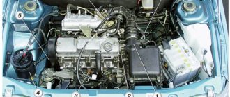
As can be seen from the above diagram, which is implemented in eight-valve injection engines, for the correct operation of the ignition system, the electronic engine control unit must be supplied with the necessary information from the sensors. The main sensor for system operation is the crankshaft position sensor . It is located on the ebb of the cylinder block next to the generator drive pulley, to the left of it, when looking at the end of the crankshaft.
Crankshaft position sensor
A timing gear disk is installed on the crankshaft pulley, which generates electromagnetic oscillations, and the sensor converts them into a pulse, this pulse is supplied to the computer. The control unit, based on the position of the crankshaft, sends a signal to the ignition module, which distributes the spark between the spark plugs.
In addition, the crankshaft position sensor sets the timing of fuel injection, so first of all we will check its condition.
- Remove the protective casing from the gas distribution mechanism drive.
Removing the timing belt protective cover
Scheme of signal receipt from the crankshaft sensor: 1 – crankshaft master disk; 2 – crankshaft position sensor; 3 – angle of rotation of the crankshaft; 4 – output signal of the crankshaft position sensor
Align the mark on the flywheel with the mark on the gearbox housing
We check the coincidence of the marks on the oil pump pulley and the tide on the cylinder block
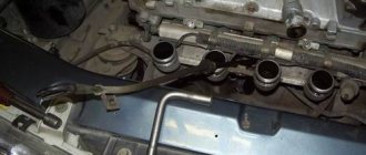
We check the coincidence of the marks on the camshaft drive toothed pulley and the timing belt cover
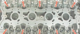
If the three marks coincide, it means that at this moment the pistons of the first and fourth cylinders are at top dead center. It is at this moment that the gap between the teeth on the drive disk should coincide with the tide on the cylinder block, and the 20th tooth from the gap should coincide with the crankshaft position sensor. It is at this moment that the sensor sends an impulse to the engine control unit, indicating to it that the piston of the first cylinder is at the top dead center of the compression stroke.
We check the completed work. Step-by-step instruction
As can be seen from the diagram above, the ignition system consists of high-voltage and low-voltage circuits. In this regard, there are several points that you need to know when checking the system.
High-voltage wires operate at a voltage of about forty thousand volts. In our case, such a voltage is not dangerous for life, but receiving a discharge even with a low current strength and such a voltage is unlikely to be beneficial for health and mood. Therefore, it is advisable to work in rubberized gloves and use tools with insulated handles.
To check the condition of the system, you will need pliers with insulated handles, a standard set of tools and a multimeter. Please note that we only check the operation of the circuits, and not the operation of the microprocessor part. This requires computer equipment and special training.
- With the ignition off, we check the contacts on all connectors in the system. First of all, the tightness of fit and contact of high-voltage wires in the ignition module.
- We remove the block from the module and check the voltage at terminals C and B. The multimeter is set to low AC current control mode. For more details, see “checking the ignition module“.
Check the voltage at terminals C and B of the ignition module
Checking ignition coil contacts 2 and 4 with a multimeter
Checking high voltage wires
This way you can check and set the ignition on a VAZ-2114 with an injection 8-valve engine with your own hands. Good luck to everyone!
Repair of distributor VAZ 2110-2112
In this article we will walk through the complete disassembly and repair of the ignition distributor sensor for the VAZ 2110, 2111 and 2112 with step-by-step actions.
Before we begin step-by-step steps to repair this device in a car, let's give it a definition of what it is.
An ignition distributor (distributor) is an electronic mechanism that distributes high-voltage pulses in the vehicle’s ignition system and transmits electricity from the ignition coil to the spark plugs, which alternately detonate the fuel in the cylinders of carburetor and injection gasoline internal combustion engines.
The procedure for repairing components of the ignition distributor of a VAZ 2110, 2111 and 2112 car:
1. First you need to remove the ignition distributor (distributor) from the car.
2. To remove the ignition distributor sensor cover, you need to unscrew the two mounting bolts. Then the slider is removed; to do this, it should be carefully pulled up.
3. The technical condition of the removed slider may vary. A slider with signs of burning, cracks, as well as significant traces of corrosion or wear of the external contact (No. 1 in the photo) must be replaced. The runner should be tightly installed on the roller. This is ensured by a spring in the form of a metal plate (No. 2 in the photo). A slider with a broken or weakened spring must also be replaced. Using an ohmmeter, you need to measure the resistance on the resistor (No. 3 in the photo), it should be strictly 1 kOhm. Otherwise, the slider changes.
4. Next, the protective screen is removed.
5. After this, you need to unscrew the screw securing the low voltage wire terminal and remove it from the ignition distributor housing.
6. Using a screwdriver, open the legs of the holder and then remove the wire fixed in it.
7. Unscrew a pair of bolts securing the support plate on which the Hall sensor is located.
8. After this, you need to remove the retaining ring from the pin on the support plate.9. To remove the vacuum corrector, you need to unscrew the screws that secure it.
10. Using a screwdriver, remove the vacuum corrector rod from the support plate pin.
11. After these steps, you can dismantle the vacuum corrector itself.
12. To remove the support plate, you must carefully lift it with a screwdriver, thereby removing it from its fixed position.
13. If scoring or significant visible wear of the bushing is detected, the support plate should be replaced.
14. Next, you need to remove the retaining ring from the camshaft, and then the thrust washer that follows.
15. After this, the spring ring holding the coupling fixing pin is dismantled.
16. If the condition of the ring can be described as torn or lost elasticity, then it must also be replaced.
17. The coupling mounting pin is knocked out using a suitable punch.
18. Next, remove the distributor drive coupling and the following adjusting washers. If the coupling has severely worn spikes or other contact elements, it must be replaced.
19. After this, carefully remove the roller with the centrifugal regulator installed on it.
20. To assess the performance of the bushings in which the roller is installed, they are visually inspected on both sides of the distributor body. If scuffing or significant wear of the bushings themselves is noticeable, then the housing complete with bushings should be replaced.
Ignition systems of the 8-valve injection VAZ-2114
You can determine the type of ignition by looking under the hood:
- If you find a breaker near the “heart” of your car (analogous to a distributor installed on contact systems), then your car belongs to the first series, and the ignition of the VAZ 2114 injector on it is non-contact, based on the breaker-distributor assembly. The ignition in such systems is set by turning the distributor degree by degree, and the results of the work depend on the experience of the performer and the availability of special equipment. So, with the help of a strobe light, the system can be debugged exactly as desired by the car owner.
- If this part is not present, then your car belongs to the representatives of the tenth family, equipped with an electronic ignition system. It is impossible to set this manually, and its operation is completely controlled by the ECU. At the same time, it is not completely unadjustable, because by connecting to an on-board computer, some of its parameters can be reconfigured to your taste, but there are only a few specialists capable of doing this correctly.
IMPORTANT! The electronic system in the VAZ 2114 is designed so that the owner does not have to maintain it, so if you do not plan to participate in racing competitions with your car, it is better not to mess with the software.
How the device works
Instead, an ignition module is used, consisting of high-energy control electronics and two coils. The advantage of the new system is that it does not require regular maintenance and maintenance, since there are no moving elements. Also, no special adjustment of the system is required. The reason lies in the presence of a controller. is the one responsible for setting up and adjusting.
Causes of ignition problems
As mentioned earlier, in order to set the ignition in the electronic system you will have to go into the “brains”, there you can also check the functionality of the sensors, so they greatly influence the operation of the system, regardless of the type of ignition.
On the electronic type, the main causes of failures are:
- Incorrect information transmitted from sensors to the ECU. If the connection to the brain and diagnostics showed strange data coming from one or more control devices, it is necessary to use a “substitution”. The easiest way is to find a car with known good sensors, install them and double-check the results. Here you need to understand that you do not need a new one, but a working sensor, because factory defects are not excluded even on a new mechanism.
- The incoming voltage - correct from a technical point of view is 5V, but if due to a violation of the mechanical integrity of the wires or another problem with the car’s electronics, this voltage changes, the sensor readings will also change after it. If this happens, the ECU begins to adjust engine operation based on incorrect data, which leads to incorrect operation of the entire mechanism as a whole. To check this breakdown, you will need a known-good system of wires leading to the sensor or a donor car into which you can install your sensor and test the system for functionality.
- Broken ECU - if the previous two options did not give a visible result, and installing your sensor and wiring in a working machine does not change its performance, only this option remains. You can try to reflash the “brain” of the car, but due to its low cost, it is better to immediately buy a new ECU and install it on the car.
Before moving on to the radical measures proposed in the third option, it is worth additionally checking the correct location of the labels. In cars with contactless ignition, this is the ignition installation of the VAZ 2114, and for cars with an electronic system, debugging is important to check the synchronization of the injection system with the gas distribution mechanism.
Work order
Before starting work, it is necessary to set information in the control unit. Sensors will help do this.
In order to set the ignition on a VAZ 2110 8 valve injector, you must have some skills related to car repair:
- Find the gas distribution mechanism and release it from the case.
- There should be a distance not exceeding 0.5 - 0.7 mm between the sensor and the crankshaft toothed disk. This is necessary so that the pulse from the sensor can pass without uninterrupted formation of sparks.
- The crankshaft pulley should remain in place. How can I check this? The marks located on the flywheel will help with this. They must match the marks on the gearbox housing. To do this, you need to turn the crankshaft.
- It is necessary to ensure that the mark located on the oil pump is aligned with the boss of the cylinder block.
- There must be a coincidence between the mark on the camshaft drive wheel and the timing belt cover.
- Pistons 1 and 4 of cylinders, provided that all points are aligned, will be in the upper position. The distance between the teeth should coincide with the boss on the cylinder block. The tooth located at the 20th place will coincide with the crankshaft sensor.
- The sensor will send a signal to the internal combustion engine control system. It will mean that the piston of the first cylinder is in the upper position in a compressed state.
Getting ready to adjust the ignition
In order to correctly set the ignition timing of the VAZ 2114 and carry out debugging, you need to prepare. The method described below does not require acrobatic agility from the owner and is quite feasible both in the uncomfortable and cramped environment of a garage and if the car enthusiast has a tummy.
IMPORTANT! Thorough preparation always speeds up the process of technical work significantly, regardless of what exactly needs to be repaired.
Preparation for debugging ignition marks is carried out as follows:
- The car is placed on a flat surface and placed on the handbrake.
- The second step is to remove the front right wheel, which will subsequently allow you to gain access to the gas distribution mechanism itself, which will speed up the work, make it convenient and easy, for this: a. unscrew the fastenings of our wheel and place a wheel chock under the diagonally opposite wheel (rear left); b. We lift the car with a jack, twist the wheel mounts completely and remove it.
- Finally, we need to remove the timing belt splash guard (if there is one, of course). By the way, you can not remove it entirely, but just unscrew the two lower fasteners, then it can be moved away without damaging it.
Removal and disassembly of the VAZ 2110 distributor
The VAZ 2110 distributor is dismantled in cases of working with the cylinder head or replacing the oil seal or bearing; for example, when replacing a slider or distributor cover, there is no need to remove the ignition distributor.
To remove the distributor from the VAZ 2110, follow the further instructions. We take out the high-voltage wires from the cover and use a Phillips screwdriver to unscrew the two screws securing the cover, then remove it. The distributor cover of the VAZ 2110 is installed in only one position, and the wire socket of the first cylinder is marked with the number “1”. The remaining wires are installed in accordance with the operating order of the cylinders - 1-3-4-2 (the direction of rotation of the slider, as well as the camshaft, is counterclockwise, looking from the side of the sensor-distributor cover).
By pulling, remove the slider. To dismantle the VAZ 2110 hall sensor assembly, disconnect the high-voltage wires, the hose from the vacuum regulator and the electrical connector
Using a 10mm wrench, unscrew the nut of the upper fastening of the hall sensor and remove the holder of the high-voltage wires
Having unscrewed two more nuts, remove the sensor-distributor and remove the rubber seal using a screwdriver.
Remove the protective screen and tighten the two screws securing the front bearing holder of the VAZ 2110 distributor
Next, unscrew the connector mounting screw and remove it
Remove the lock washer of the vacuum regulator rod of the distributor and unscrew the two screws securing it
Remove the vacuum regulator and front bearing holder with Hall sensor VAZ 2110
Unscrew the two screws and remove the Hall sensor. Next, we disassemble the unit to replace the centrifugal regulator or oil seal of the VAZ 2110 distributor
Using a screwdriver, remove the spring, use a 2.5 mm drill to knock out the coupling pin and remove it
We take out the centrifugal regulator and knock out the VAZ 2110 distributor oil seal through two holes in the body
We press in the new distributor oil seal with a piece of suitable pipe, then install a washer on it and core it in several places.
Marks and direct adjustment
When the preparation is completed and the car is ready to work with it, you can begin to set the ignition marks of the VAZ 2114. The task of the procedure is to check the synchronism of the system (correlation of the camshaft, crankshaft and injection timing), with some nuances for the electronic system.
For electronic ignition systems, there is a small nuance - the need to check the distance from the master disk to the sensor. Normally, this distance should not exceed 0.7 mm, but should not be less than 0.5 mm. You can use a valve feeler gauge to check.
The further procedure for the electronic ignition system is as follows:
- We look into the mark hatch and align the gearbox housing mark with the flywheel mark by turning the crankshaft.
- We find the mark on the oil pump pulley and make sure it matches the tide of the cylinder block.
- Align the camshaft pulley mark with the head boss.
- The work is completed, to check the correct setting, check that the gap on the disk coincides with the tide of the cylinder block, and the twentieth tooth with the crankshaft position sensor. If everything matches, you have successfully completed the task.
Checking and adjusting the marks on the eight-valve injection valve
To adjust the ignition you will need the following tools:
- jack;
- wheel wrench;
- key (head) 10;
- key to 13;
- key to 17;
- key to 19;
- large slotted screwdriver;
- flashlight.
It is also advisable to involve an assistant.
Work order:
- We install the car on a horizontally flat surface. We block the rear wheels.
- Using a wheel wrench, unscrew the bolts securing the right wheel and jack it up. Unscrew the bolts completely and remove the wheel.
- Open the hood, use a 10 mm socket to unscrew the three bolts securing the front protective cover of the timing drive. Let's take it off.
- Using a 13mm wrench, loosen the generator belt tensioner nut and remove the belt.
- Using a 19mm wrench, unscrew the nut securing the generator pulley. To do this, you will need an assistant, whose task is to hold the brake pedal in the cabin when fifth gear is engaged. When all this is done, you will have the opportunity to see all the ignition marks of the VAZ-2110.
- We rotate the front wheel so that the lug on the camshaft gear clearly coincides with the protrusion on the rear timing drive cover. When they are aligned, take a flashlight and look at the position of the mark on the crankshaft pulley. It should point to the test point located on the oil pump cover. If they coincide, without letting go of the flashlight, we move to the engine compartment and compare the position of the marks on the flywheel crown. When the ignition is set correctly, it should also be aligned with the mark on the gearbox housing. In this case, everything is in order with the valve timing. The ignition marks are in their places. If, although the marks on the camshaft and the rear cover coincide, the tide on the crankshaft gear does not coincide with the point on the oil pump cover, it is necessary to make an adjustment.
- Using a 17 key, unscrew the timing belt tensioner pulley. We remove the belt.
- Without touching the timing shaft gears, rotate the wheel until the mark on the crankshaft pulley coincides with the marked point.
- We insert a slotted screwdriver into the inspection window so as to immobilize the flywheel.
- Carefully, so as not to change the settings, put the belt on the camshaft gear and crankshaft pulley. We tighten the tensioner pulley and fix it. Check to see if the marks have gone astray. If necessary, repeat the procedure.
Useful video
You can find interesting information by watching the additional video below: https://www.youtube.com/watch?v=pNyBny-_HoQ
On a car with contactless ignition, everything is even easier; you don’t have to remove the wheels, but you will need an assistant. It is necessary to find the compression stroke of the fourth cylinder. To do this, insert a rubber cone into the spark plug hole and turn the ratchet. Pushing out the cone will mean that the compression stroke has been found.
Having illuminated the spark plug hole, we align the longest mark of the cover with the mark of the pulley. We set the breaker to the appropriate clock and check the operation of the system according to the fourth point described above.
Starter problems
Many VAZ 2110 owners had a situation where the starter did not turn after inserting and turning the key. They heard characteristic clicks. This indicates that the solenoid relay is not working.
But the fact is that the “ten” does not have a starter relay, that is, an ignition relay as such. Instead, a solenoid relay works. It is supplied with a positive contact from the ignition switch. Mount this relay to the starter. It has a round shape and is approximately half the size of the starter itself.