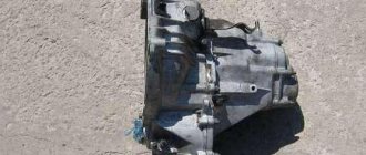
In 1979, the Volzhsky Automobile Plant began producing the VAZ-2105, one of the modifications of the classic family. This model is a “long-liver”, since its production lasted longer than any of the “Classics” - 30 years. It is noteworthy that before the appearance of this model, at first all the predecessors of this family until 1976 were equipped with one single gearbox - from the VAZ-2101. Since 1976, the gearbox has been modernized, but it was intended only for the VAZ-2106 and Niva. The main difference lay in the changed gear ratios; later this gearbox was designated as a box with a “high” row.
For the VAZ-2105, the box was redesigned again, which affected the gear ratios. The new gearbox became “intermediate” in this indicator between the 2101 and 2106 gearboxes. Subsequently, it was the VAZ-2105 gearbox that was left and all cars began to be equipped with it, and the production of the first two versions was stopped, and there were two versions of 2105 - a 4-speed and a five-speed. Also, over time, the index of this box has changed - instead of 2105, it began to be labeled as 2107 and 21074 (5-speed).
Gearbox device
In general, the concept of “remaking” the box is not entirely correct, since the design of the VAZ-2105 gearbox with 4 speeds was practically no different from the same gearbox 2101. The 2105 gearbox has a three-shaft layout, with constant gear meshing and manual control. Externally, the Kopeika and Pyaterki checkpoints can be distinguished almost only by the markings on the body of the box.
The VAZ-2105 gearbox diagram with 4 stages is presented below, and structurally it does not differ from modifications 2101 and 2106:
Since the box from the VAZ-2105 is structurally similar to the 2101, the kinematic diagram of the gearbox is the same. But the gear ratios are different; on 2105 gearboxes they are:
- 1st – 3.67;
- 2nd – 2.10;
- 3rd – 1.36;
- 4th – 1.00;
- Rear – 3.53;
As for the differences in the design between gearboxes 2105 and 2101, they mainly come down to different numbers of teeth on different gears. So, on the intermediate shaft of the gearbox, a 1st speed gear with 14 teeth is used (15 for 2101), and their inclination angle is greater. The constant mesh gear of this shaft has 28 teeth (29 for 2101). The input shaft uses an 18-tooth gear (19 for 2101). Because of these features, the shafts with gear blocks of these two gearboxes are not interchangeable if you try to install them separately. But in the case of a complex replacement - the input shaft along with the intermediate shaft and all gear blocks, then installation is quite possible. As for the secondary shaft, modification 2105 differs from shaft 2101 in the first gear gear (its teeth have a different angle, although their number is the same, and its diameter is also slightly larger).
The device of a five-speed gearbox in the VAZ-2107.
A car's manual gearbox is a rather complex device. In general, it consists of three main parts - shafts. Each of them has its own purpose:
- — the primary (drive) shaft on which the drive gears and synchronizers that equalize their speed are mounted;
- — intermediate shaft
- - secondary (driven) shaft, also equipped with gears.
These mechanisms and components are protected by a common housing on three sides, and the handle of the gear control lever is located on top.
To understand the principle of operation of a five-speed gearbox, you should consider its structure in detail.
Primary shaft
- design equipped with gears. It is mounted on a bearing located in the cavity of the gearbox housing.
Manual transmission secondary shaft
continues the drive shaft. The gears of the first three gears are fixed there. They are all different diameters, and it is due to this that the difference in gear ratios is achieved.
Table: five-speed gearbox gear ratios
| broadcast | meaning |
| first | 3,67 |
| second | 2,10 |
| third | 2,0 |
| fourth | 1,0 |
| fifth | 0,82 |
The rotation of the secondary shaft is carried out not by one, but by three bearings, one of which is installed directly in the drive shaft, and the remaining two are inside the crankcase and directly in the rear housing cover.
Intermediate shaft
also rotates on three ball bearings, and the gears form a single whole with it. This unit transmits a moment of force of a given value from the drive shaft to the driven one.
The reverse gear is mounted on a separate small shaft connected to the driven transmission shaft through several splines.
The driver shifts gears using so-called forks, driven by a lever located inside the cabin, to the right of the driver. When the position of the lever changes, its hinge engages with a recess of a certain rod, which is secured with the other side to the fork. The fork itself is located in the groove of the corresponding gear. When the shift lever moves, the fork also moves, whereby the desired gear on the driven shaft meshes with a specific intermediate gear. Consequently, the rotation of the driven shaft of the box acquires the speed that corresponds to the gear ratio of the connected gears.
When shifting into reverse, the fork comes into contact with the reverse idler gear. To turn it on, you need to push the gearshift lever down.
The filler hole for transmission oil in the box of the VAZ-2107 car is located on the left in the body and is closed with a sealed plug. To avoid oil leakage from the manual transmission pan, all bearings are protected by seals.
A mechanical five-speed three-shaft gearbox is a complex mechanism, so disassembling and repairing it should not be done with your own hands or at home.
The design of the VAZ 2107 car involves equipping it with a five-speed gearbox, the schematic diagram of which is presented below.
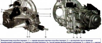
Gearbox device "VAZ 2107"
AvtoVAZ designers used a four-speed transmission used on earlier models of the Lada family as the basis for creating the “Seven” transmission. The differences in the new gearbox are not significant and are expressed in a change in the appearance and geometric shape of the rear cover caused by the addition (at the end of the driven shaft) of fifth-stage elements.
The increase in the number of gears provided the following positive aspects during the operation of the car:
- Expanding the speed range made it possible to operate the vehicle in the most economical modes.
The operational period of the power unit has been increased.
The introduction of an additional gear did not change the size of the gear ratios in comparison with the basic version and the number of shafts (three), which makes most of the parts of the new and old gearbox interchangeable.
The VAZ 2107 gearbox consists of several main structural elements:
- The input shaft of the VAZ 2107 gearbox is absolutely identical to the shaft used in the transmission of a four-speed gearbox.
An intermediate shaft with a threaded hole for fastening the rear and fifth gears, located at the rear end.
The secondary shaft of the VAZ 2107 gearbox, which differs from the “predecessor” in the fifth-stage elements placed on it.
Aluminum crankcase with stamped steel cover.
The gearbox is lubricated using transmission oil poured into the crankcase (1.35 liters). To seal the ends of the primary and secondary shafts, special oil seals (cuffs) are used.
Difference between 4-speed and 5-speed gearboxes
As noted, the VAZ-2105 was equipped with two gearboxes - 4 and 5 speeds. At the same time, they took the 4-speed version as the basis for creating a 5-speed gearbox and modified it a little. Therefore, the gear ratios of the five-speed gearbox up to 4th speed are identical, but the added 5th speed has a gear ratio of 0.82. That is, this direct box still has 4th gear.
Let's take a more specific look at the differences between the five-speed and the four-speed on the VAZ-2105, and there are several of them:
- the 5-speed gearbox uses a slightly different rear gearbox cover, where the 5th speed gear block is located;
- the intermediate shaft has a threaded hole for mounting the 5th and reverse speed gear block;
- the presence of a 5th gear gear block with a synchronizer and a reverse gear, and the output shaft is slightly shortened;
- The rear speed intermediate gear axis of the 5-speed version is secured with a nut;
- a slightly different gear shift drive, as well as a speed selection mechanism;
- The sensor for turning on the rear speed light is also different;
Since the 4-speed version was the basis for creating the 5-speed gearbox, it is quite possible to upgrade the 4-speed gearbox yourself at home, for which you should replace and add the specified gearbox components.
As for the control of the VAZ-2105 gearbox, the switching pattern is no different from the VAZ-2106 or any other modification with a 4-speed gearbox. In a 5-speed gearbox, to engage the last speed, it is enough to move the gearshift lever as far as possible to the right and push it forward, that is, in the direction opposite to the rear speed. Below are shown the switching diagrams for both gearbox modifications:
In general, the KPP-2105 is very reliable and can operate for a long time without any maintenance. In addition, it has good maintainability and repairs are not so difficult. Replacing the 2105 gearbox is usually done in case of wear of the bearing seats in the housing or if it is damaged - breakdown, cracks. In case of other breakdowns (wear or damage to gears, bearings, shafts, etc.), the functionality of the unit can be restored by replacing the broken elements. Also, replacement can be carried out in the case of installing a 5-speed modification instead of a 4-speed one, in the case where the unit was purchased as an assembly, and not only those elements that allow you to modernize the old gearbox.
But in any case, whether it’s a replacement, modernization or repair, nothing can be done while the gearbox is installed on the car. In any case, the unit will have to be dismantled, and you need to know how to remove the box.
Gear shift mechanism
Numbers 1, 2 and 16 are the speed forks: 3rd, 4th, 1st and 2nd, rear and 5th. Fork rods No. 5, No. 7 and No. 9 are controlled by lever No. 8, which is located in the car interior.
The gear shift works according to the following scheme: if lever No. 8 changes position, the hinge engages with a recess located on one of the axes, the other end of which is in rigid engagement with fork No. 3. It, in turn, fits into the recess on the forward gear at numbers 16, 23, 24, 25 or number 20 for the rear. Lever 8 moves the fork, which leads to engagement of the required secondary shaft gear with the appropriate intermediate gear. The torque transmission circuit is closed and the secondary axis rotates at a speed that corresponds to the gear ratio of the meshed gears. If you engage reverse gear, then, unlike others, the lever will be pushed down while driving.
As you can see, the design and operating diagram of the VAZ 2107 five-speed gearbox is quite complex, as a result, we do not recommend repairing it without the necessary knowledge. It is better to entrust this procedure to professionals.
Page 1 of 3
The basic repair work for a five-speed gearbox is similar to that for a four-speed gearbox. Disassembly and assembly of a four-speed gearbox is described in the article - “Transmission Repair”.
Since 1992, five-speed gearboxes do not have a washer installed on the secondary shaft and the configuration of the secondary shaft and the 5th gear synchronizer clutch hub has been changed. On the secondary shaft, the diameter for the hub was 28, became 25 mm; The width of the hub landing part has become larger and the landing diameter has been reduced from 28 to 25 mm.
The specified parts are not interchangeable with previously produced ones, therefore, when repairing a gearbox of an “old” design, we follow the following rules:
If the washer is changed, then we install the secondary shaft and hub of the “old” design;
If, instead of a secondary shaft or hub, parts of the same name of a “new” design are installed, then we replace them as a whole, that is, when replacing the hub, we also replace the secondary shaft and vice versa. In this case, we do not install the washer.
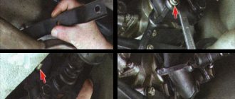
| 1. To facilitate the removal and subsequent installation of the elastic coupling, wrap it tightly with tape. | You can use a large band clamp to clamp the elastic coupling |
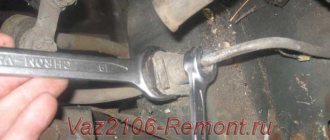
| 2. Having unscrewed three nuts with two 19mm wrenches and removed three bolts, remove the coupling. Remove the elastic coupling flange, gearbox support, and speedometer drive. | 3. Using a 10mm wrench, unscrew the three nuts securing the ball joint of the gearshift lever and... |
| 4...remove the lever from the studs of the rear gearbox cover. | 5. Using the “27” key, turn off the reverse light switch and... |
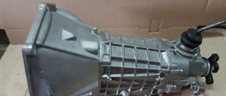
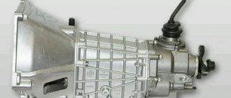
The domestic car VAZ-2107, popular among drivers, is equipped with a four- or five-speed manual gearbox. But a four-speed gearbox can only be seen on cars of the first releases. Subsequently, the VAZ-2107 of all modifications was equipped with a five-speed manual three-shaft gearbox with a two-shaft cardan transmission, transmitting engine torque from the gearbox to the driving rear axle.
Gearbox VAZ 2107 5 mortar diagram
The five-speed gearbox is designed to improve engine performance, increase its efficiency and expand the speed range. This type of box is made on the basis of a four-speed one, but due to the appearance of a fifth gear, some design changes have been made to the rear end of the secondary shaft and the rear end of the intermediate shaft. The gear ratios of the first four gears are identical to the four-speed gearbox. The fourth gear is also direct, and the fifth, with minimal engine torque, allows you to develop maximum speed. Its gear ratio is 0.82.
Removing the gearbox from the car
In fact, dismantling the gearbox from a VAZ-2105 is not a very difficult operation and it is quite possible to do it yourself, having only a basic tool:
- Sets of wrenches (open-end, socket), heads with knobs, extensions;
- Screwdrivers;
- Rags;
- WD-40 product;
- Wooden block;
- Jack;
Removal of the box must be carried out on an inspection hole or overpass - there is no other way to dismantle it. It is noteworthy that the removal technology is identical for all modifications of this car - with a 5-speed gearbox or 4-speed, carburetor version or VAZ-2105 injector.
The sequence of actions is as follows:
- We place the car in the pit, immobilize it with wheel chocks, set the gearbox to neutral, disconnect the ground from the battery;
- The first part of the work is carried out in the salon. First, remove the radio panel and decorative casing and everything else that is located near the gearshift lever. Then pull up the lever to provide access to the clamping clamp. Holding it in this position, use a screwdriver to pry up the latch and remove the lever;
- We dismantle the spacer bushing, for which we use screwdrivers to open its fixing petals and tighten them;
- We remove the plastic cover with the lever boot, for which we unscrew the screws along its perimeter;
- We climb under the car. First of all, we dismantle the exhaust system of the car. To do this, we tighten all its fasteners and disconnect the muffler from the exhaust manifold pipes;
- Unscrew the cardan shaft from the elastic coupling. To make work easier, jack up the rear of the car a little, which will allow you to rotate the shaft when unscrewing the fasteners, providing easy access to the bolts. Afterwards we lower the shaft down;
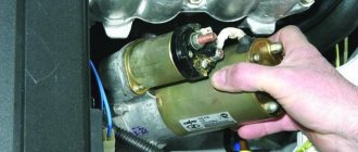
- Remove the starter;
- We remove the clutch drive from the crankcase. In this case, it is not necessary to completely remove the working cylinder; it is enough to disconnect it from the crankcase and move it to the side;
- Disconnect the speedometer drive cable and the reversing light wires from the box;
- We install a wooden beam under the box, which will support it, so you should choose the right length;
- Unscrew the bolts securing the clutch housing inspection cover
- Unscrew the nuts securing the rear cross member of the gearbox;
- We check the reliability of the support installation. After this, we unscrew the fastening elements of the clutch housing to the power unit;
- Holding the box with your hand, using a flat screwdriver and a pry bar we pull off its mounting pins, but this is not enough, you still need to completely remove the input shaft from the clutch driven disc. To do this, already holding the gearbox with both hands, move it as far back as possible, and then lower it.
And then the unit is replaced, modernized or repaired. In the last two cases, the VAZ-2105 gearbox is disassembled, worn elements are replaced, a 5th gear gear block is added, etc.
To put the gearbox in place, perform the described steps in reverse order. In this case, before seating the box, it is recommended to lubricate the splines of the input shaft with a thin layer of Litol to make it easier to fit into the driven disk.
When installing it back, if the gearbox does not go into place, you need to push it back, turn the shaft and try to seat it again. You may have to do this several times to get the shaft splines to line up with the splines in the disc.
Article on the topic - Repair of the gearbox of a VAZ-2105 car
When designing the VAZ-2105, the designers slightly redesigned the gearbox, changing the gear ratios of each gear. But in general, the design of the gearbox of this car was not very different from previous modifications.
The first gearboxes were four-speed, three-shaft, with constant mesh gears and synchronizers in all forward gears. Later this box was modified by adding an additional 5th speed. Moreover, the 4-speed modification was taken as the basis for its creation, so the five-speed direct transmission remained in 4th speed.
Subsequently, the gearbox developed for the VAZ-2105 became the main one and was equipped with all cars of the classic family until their production ended. In the future, we will consider the maintenance of a 5-speed gearbox, since the repair of a 4-speed VAZ-2105 gearbox is done basically in the same way as a five-speed gearbox, due to the fact that the design of these versions of the gearbox is largely similar, then maintenance and repair operations - identical. We will also find out how to convert a 4-speed modification into a five-speed one.
The main advantage of such a gearbox was the high reliability of the unit and unpretentiousness in operation, so repair of the VAZ-2105 gearbox is not required very often; it is capable of working out a significant service life without any special intervention and with minimal maintenance. Another positive quality is the maintainability and availability of spare parts and repair kits, so repair of the 2105 gearbox can be performed even in a garage with a basic set of tools.
Do-it-yourself troubleshooting of the gearbox on a Lada 2105 car, checking and troubleshooting the gearbox of the Lada 2107, replacing and checking the oil in the gearbox of the Lada 2104, repairing the VAZ 2104, VAZ 2105, VAZ 2107 gearboxes. Section on repairing the Lada 2104 transmission and rear axle. Repair of cardan, clutch of Lada 2105. Differential of Lada 2107.
Disassembly. Wash the gearbox and install it on a stand. Drain the oil and remove the bottom cover with gasket. Remove the clutch release fork, and from the guide sleeve of the front gearbox cover, remove the clutch assembly with bearing and connecting spring.
Internal view of the clutch housing. Red arrows indicate the nuts securing the clutch housing to the gearbox; The white arrow indicates the hole in the front cover for releasing oil from the gearbox housing to prevent oiling of the clutch discs
Remove the clutch housing with gasket and gearbox front cover (along with the oil seal and spring washer). Remove the speedometer drive with the gasket and the reverse light switch, being careful not to deform its housing. Remove the bolt securing the 3rd and 4th gear shift fork. Install clamp 41.7816.4068 on the input shaft or engage two gears at the same time. This will prevent rotation of the primary, secondary and intermediate shafts and will allow subsequent operations to disassemble the VAZ 2107 box.
Removing the retaining ring
Remove the retaining ring from the end of the secondary shaft of the VAZ 2105 gearbox.
Removing the centering ring of the elastic coupling of the cardan shaft using ejector A.40006/1 and puller A.40005/4
Having straightened the lock washer, unscrew the nut a few turns to move the centering ring of the elastic coupling, and tighten the nut again. Using a pusher A.40006/1 with a puller A.40005/4, remove the centering ring of the elastic coupling of the cardan shaft from the end of the secondary shaft.
Removing the elastic coupling flange using a puller A.40005/3/9B/9C: 1 - elastic coupling flange; 2 — bolts securing the device to the flange; 3 — strip 9C of puller A.40005/3; 4 — puller A.40005/3
Remove the elastic coupling centering ring seal from the end of the secondary shaft, unscrew the nut and remove the elastic coupling flange using a puller A.40005/3/9B/9C.
Internal view of the rear cover of the gearbox: 1 - screw with an eye for fastening the release spring of the gear shift lever; 2 — lever release spring; 3 — gear shift lever; 4 — screw for limiting the lateral travel of the lever. The arrow indicates the direction in which you need to move the lever to disengage it from the heads of the gear shift rods and remove the rear transmission cover
Remove the rear cover of the gearbox by unscrewing the nuts securing it and screw 4 for limiting the lateral travel of the lever and moving the VAZ 2107 gear shift lever to the left to free it from the gear shift rods. Remove the rear bearing from the output shaft. Remove the drive gear of the speedometer drive of the VAZ 2107, VAZ 2105, VAZ 2104. Remove the fork with the remote sleeve from the reverse control rod. Remove the VAZ 2105 reverse intermediate gear from the axle.
Removing the reverse gear snap ring from the intermediate shaft
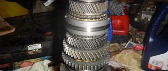
Remove the reverse drive gear retaining ring from the countershaft; Remove the gear and spring washer. Remove the reverse driven gear retaining ring from the secondary shaft by pressing the spring washer with mandrel 41.7816.4069 to relieve the load on the retaining ring. Remove the reverse driven gear and spring washer. Using shaped mandrels (such as screwdrivers) and rod drifts, remove the front and rear intermediate shaft bearings from the gearbox housing. Make marks on the inner rings of the double-row front bearing, according to which these rings should be installed in their original places in the outer ring of the bearing.
Removing the intermediate shaft from the gearbox housing
Remove the VAZ 2104 intermediate shaft from the gearbox housing by tilting it.
Gear shift drive VAZ 2104: 1 — reverse fork; 2 — tension spring of the gear shift lever; 3 — guide cup of the lever; 4 — ball joint of the lever; 5 — gear shift lever; 6 - spherical washer; 7 — lever spring; 8 — retaining ring; 9 — damper locking sleeve; 10 — elastic damper bushings; 11 — damper spacer bushing; 12 — damper thrust pad; 13 — gear shift lever rod; 14 — fork for switching off 3rd and 4th gears; 15 — fork for switching off 1st and 2nd gears; 16 — fork rod for 1st and 2nd gears; 17 — fork rod for 3rd and 4th gears; 18 — reverse fork rod; 19 — blocking crackers; 20 — clamp cover; 21 - bushing; 22 — clamp spring; 23 — retainer ball; 24 — rear cover of the gearbox; 25 — reverse light switch; 26 – remote bushing for the reverse fork rod
Remove the cover 20 of the rod clamps together with the gasket, take out the springs and balls of the clamps. Remove rod 18 for reverse gear and rod 17 for shift fork for 3rd and 4th gears from the gearbox housing. Unscrew the bolt securing the forks of 1st and 2nd gears, remove the rod and forks. When removing the rods, simultaneously remove three locking blocks 19.
Unscrewing the screws securing the locking plate of the intermediate bearing of the secondary shaft with a drill-screwdriver. The arrow shows the direction of the impact stroke of the screwdriver cage; use a hammer
Remove the secondary shaft idler bearing retainer plate and the reverse idler gear shaft.
Removing the input shaft from the gearbox housing
Using mandrels (like screwdrivers), remove the input shaft along with the bearing and synchronizer ring and remove the needle bearing from the front end of the output shaft.
Removing the secondary shaft from the gearbox housing
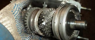
Knock the secondary shaft out of the intermediate bearing, remove the intermediate bearing and, tilting it, remove the secondary shaft assembly with gears, clutches and synchronizer rings from the crankcase. Remove the synchronizer clutch for third and fourth gears of VAZ 2104, VAZ 2105, VAZ 2107 from the shaft.
Parts of the input shaft: 1 - retaining ring; 2 - spring washer; 3 - bearing; 4 - input shaft; 5 — synchronizer spring; 6 — synchronizer blocking ring; 7 - retaining ring; 8 - bearing
Disassemble the input shaft:
— remove the locking ring 7, the blocking ring 6 and the synchronizer spring 5; — install the shaft on the press and, using a mandrel 41.7816.4069, compress the spring washer 2, remove the locking ring 1, then the spring washer and bearing 3.
Secondary shaft parts: 1 - retaining ring; 2 - spring washer; 3 — synchronizer hub; 4 — synchronizer clutch; 5 - retaining ring; 6 — synchronizer blocking ring; 7 — synchronizer spring; 8 — washer; 9 — gear III gear; 10 - secondary shaft; 11 - 2nd gear gear; 12 — washer; 13 — synchronizer spring; 14 — blocking ring; 15 — retaining ring; 16 — synchronizer hub; 17 — synchronizer clutch; 18 — retaining ring; 19 — synchronizer blocking ring; 20 — synchronizer spring; 21 — washer; 22 — 1st gear gear; 23 — bushing of the 1st gear gear; 24 - bearing; 25 — reverse gear; 26 — spring washer; 27 — retaining ring; 28 — speedometer drive gear; 29 — rear bearing; 30 — oil seal; 31 — elastic coupling flange; 32 - nut; 33 – seal; 34 - centering ring; 35 — retaining ring
Disassemble the secondary shaft: - remove from the rear side of the shaft gear 22 of the 1st gear with sleeve 23, hub 16 with a sliding clutch for switching 1st and 2nd gears, gear 11 of the 2nd gear together with the synchronizer blocking ring 14;
Installation of the retaining ring on the secondary shaft: 1 - mandrel 41.7816.4069; 2 - retaining ring; 3 - support half-ring; 4 - spring washer; 5 — press rod
— install the secondary shaft with a mandrel 41.7816.4069 on the press, place support half-rings 3 under the third gear gear, and, pressing the mandrel on the spring washer, remove the locking ring 2, then the spring washer 4, the hub of the sliding clutch for shifting the third and fourth gears and the third gear transfers. Disassemble the gear shift lever and rear cover:
Parts of the gear shift lever: 1 - tension spring bolt; 2 — washer; 3 — tension spring; 4 - gasket; 5 — guide cup; 6 - gasket; 7 — washer; 8 — limit bolt; 9 — gear shift lever; 10 — ball joint; 11 - spherical washer; 12 - spring; 13 — support washer; 14 — retaining ring; 15 — gasket; 16 - flange; 17 — spring washer; 18 - nut; 19 — cuff; 20 — inner cover; 21 — lever rod; 22 — handle; 23 - thrust pad; 24 - elastic bushing; 25 — spacer sleeve; 26 — elastic bushing; 27 - locking sleeve
— remove the cover 20 of the lever, then the locking ring 14, washer 13, spring 12 and spherical washer 11; — disconnect the tension spring 3 of the lever from the eye of bolt 1; — remove the cuff 19, unscrew the nuts securing the flange 16 and remove the lever together with the flange, support 10 and cup 5.
The assembly of the VAZ 2104, VAZ 2105, VAZ 2107 gearbox is carried out in the reverse order of disassembly. Please note that: - spring 22 of the reverse fork rod clamp ball differs from others in elasticity, it is painted green or has a cadmium coating; — when installing the clutch housing with the front cover of the Lada Classic gearbox, the hole in the front cover should be located like this; — before installation, coat the working surface of the oil seals with LITOL-24 lubricant; — when assembling the secondary and intermediate shafts, use mandrels 41.7853.4028, 41.7853.4032, 41.7853.4039;
Installation of the reverse gear retaining ring on the secondary shaft: 1 - spring washer; 2 — mandrel 41.7816.4069; 3 - locking ring; 4 - secondary shaft reverse gear
— when installing the reverse gear retaining ring on VAZ 2104, VAZ 2105, VAZ 2107, use mandrel 41.7816.4069.
Gearbox service
But first you should consider the maintenance that needs to be carried out on this unit. There is only one thing - checking the level of lubricant and, if necessary, topping it up to the required level.
A manual transmission itself is not demanding, so the lubricant used in it performs only one function - it lubricates the component parts of the unit. Therefore, the oil in the box should be changed every 60 thousand kilometers.
Article on the topic - Construction, removal and disassembly of the VAZ-2105 gearbox
Before servicing the gearbox, you should know what kind of oil to pour into the VAZ-2105 gearbox. The transmission of this car requires gear oil with an API quality level of GL-5 or higher and a viscosity of 75W-90 or 85W-90 according to the SAE classification. The oil volume in the gearbox is 1.35 liters. — more about gear oil.
Checking the oil in the box is not difficult, but to do this, the car should be placed on an inspection hole or overpass.
And then the actions are as follows:
- On the left side of the gearbox housing (in the direction of travel of the car) we find the control filler plug (located just above the bottom cover of the box);
- Use a rag to remove dirt around the plug;
- Using a wrench of the required size, unscrew the plug;
- You can find out the level using a small mirror and a flashlight, a screwdriver or even your finger, in general, whatever is convenient. The lubricant level is considered normal if the oil reaches the bottom edge of the hole;
- If the oil level is below the level, use a technical syringe to bring it up to normal (as soon as the oil begins to flow out of the hole, tighten the plug);
Checking and adding lubricant to the gearbox should be “cold”. If maintenance is carried out immediately after a trip, it is necessary to allow time (10-15 minutes) for the oil to completely drain, otherwise the level will be incorrect when checking.
If the time has come to change the oil, then first drain the used lubricant - clean the bottom cover of dirt, place a plastic container and unscrew the drain plug.
Then wait until the oil has completely drained and tighten the plug.
And then everything is done in the same way as when checking and replenishing the level, only you will have to pump the required amount of oil into the box with a syringe.
After replacement, you should not immediately dispose of the waste; before doing so, it is better to check it. To do this, take a magnet, tie a thread and lower it into a container with old oil. Next, you should move the magnet along the bottom. Then we take it out and examine it. If a large amount of metal shavings is found on the magnet, this may indicate the appearance of intense wear, and in this case, overhauling the gearbox and troubleshooting the components will not be superfluous, since it will allow identifying and eliminating the malfunction at an early stage.
Removal and installation of the VAZ 2105 Zhiguli gearbox
- Repair manuals
- Repair manual for VAZ 2105 (Zhiguli) 1980-1992.
- Removing and installing the gearbox
Elastic coupling connecting the propeller shaft to the gearbox
| 1 – bolts securing the propeller shaft flange to the elastic coupling; 2 – nuts of bolts securing the flange of the secondary shaft of the gearbox to the elastic coupling; 3 – device A.70025; 4 – elastic coupling; 5 – cross member of the rear engine mount |
Removal
| EXECUTION ORDER |
↓ Comments ↓1. Vehicle operation 1.0 Vehicle operation 1.1. Starting the engine 1.2 Controlling the gearbox 1.3 Driving the vehicle 1.4 Braking and parking 1.5 Operating a new vehicle 1.6 Adjusting the ignition timing 1.7 Precautions when operating the vehicle 1.8 Caring for the body 1.9 Storing the vehicle 2. Car maintenance 2.0 Vehicle maintenance 2.1 Maintenance operations 3. General information 3.0 General data 3.1 Technical characteristics of vehicles 3.2. Controls 3.3. Control of interior ventilation and heating 3.4 Tightening torques for threaded connections 3.5 Tools for repair and maintenance 3.6 Used fuels, lubricants and operating fluids 3.7 Basic data for adjustments and monitoring 4. Engine 4.0 Engine 4.1 Possible malfunctions, their causes and methods of elimination 4.2 Removing and installing the engine 4.3 Disassembling the engine 4.4 Assembling the engine 4.5 Bench tests of the engine 4.6 Checking the engine on the car 4.7. Cylinder block 4.8. Pistons and connecting rods 4.9. Crankshaft and flywheel 4.10. Cylinder head and valve mechanism 4.11. Camshaft and its drive 4.12. Cooling system 4.13. Lubrication system 4.14. Power system 4.15. Carburetor 2105-1107010 4.16. Carburetor 21051-1107010 5. Transmission 5.0 Transmission 5.1. Clutch 5.2. Gearbox 5.3. Cardan transmission 5.4. Rear axle 6. Chassis 6.0 Chassis 6.1. Front suspension 6.2. Rear suspension 6.3. Shock absorbers 7. Steering 7.0 Steering 7.1 Possible malfunctions, their causes and methods of elimination 7.2. Inspection, check and adjustment of the steering 7.3. Steering gear 7.4 Steering gear rods and ball joints 7.5 Bracket for pendulum arm 8. Brakes 8.0 Brakes 8.1 Possible malfunctions, their causes and methods of elimination 8.2. Checking and adjusting the brakes 8.3 Clutch and brake pedal bracket 8.4 Vacuum booster 8.5. Main cylinder 8.6. Front brakes 8.7. Rear brakes 8.8. Rear brake pressure regulator 8.9. Parking brake 9. Electrical equipment 9.0 Electrical equipment 9.1 Possible malfunctions, their causes and methods of elimination 9.2 Circuits protected by fuses 9.3. Battery 9.4. Generator 9.5. Starter 9.6. Ignition system 9.7. Lighting and light signaling 9.8. Sound signals 9.9. Windshield cleaner 9.11. Heater fan electric motor 9.12. Control devices 9.13. Carburetor pneumatic valve control system 10. Body 10.0 Body 10.1 Possible malfunctions, their causes and methods of elimination 10.2. Doors 10.3. Hood, trunk lid, bumpers 10.4. Body glazing, windshield and headlight glass washers 10.5 Instrument panel 10.6. Seats 10.7. Heater 10.8. Body frame repair 10.9. Paint coatings 10.10. Body anti-corrosion protection 11. Car modifications 11.0 Vehicle modifications 11.1. Features of repair of VAZ-21051 and VAZ-21053 cars 11.2. Features of repair of VAZ-2104 and VAZ-21043 cars 11.3 VAZ-21044 cars with a fuel injection system 11.4. Central fuel injection system design 12. Electrical circuits 12.0 Electrical diagrams 12.1 Interactive electrical diagram of the VAZ-2105 car 12.2 Electrical diagram of the VAZ-2104 car 12.3 Electrical connection diagram of the injection system 12.4 Connection diagram of the instrument cluster 12.5 Connection diagram of the brake system warning lamps 12.6 Connection diagram of the headlight cleaners and washers 12.7 Connection diagram of the heater fan motor 12.8 Diagram inclusion windshield cleaner and washer 12.9 Diagram for switching on direction indicators and hazard warning lights |
Common faults
Now let's go over the main malfunctions that can occur with the gearbox. There are not many of them, but most of them are eliminated using the transmission removed from the car.
So, the main malfunctions of the VAZ-2105 gearbox are:
- Increased noise when the gearbox is operating (at a certain speed or at all);
- Difficulty switching to another speed;
- Unclear switching, speed loss;
- Lubricant leaks;
In turn, each malfunction can have several causes.
Noise Removal
The noise of the VAZ-2105 gearbox can occur due to wear of bearings, wear of gear teeth and gears, as well as synchronizers, and axial displacement of the shafts relative to each other.
If such a problem occurs, it will be necessary to remove the transmission from the car, since it cannot be repaired otherwise. Note that eliminating noise is one of the most difficult operations to perform, since it requires complete disassembly and reassembly of the gearbox with replacement of worn elements.
In addition to the standard set of keys and screwdrivers, you will additionally need a universal puller. Next, we’ll look at how to completely disassemble a VAZ-2105 5-speed gearbox.
So, all work is done on the removed gearbox:
- Drain the oil and remove the bottom cover. We immediately assess the condition of the gear teeth. If their damage is not noticeable, most likely the noise is coming from the bearings;
- We check the position of the gearshift lever (it should be in neutral), after which we dismantle the gear shift mechanism (link) from the gearbox;
- Remove the cover of the clamps and remove the springs and balls;
- We remove the elastic coupling from the secondary shaft, and then its hub (to unscrew the hub nut, unscrew the bolt securing the 3rd and 4th gear forks, engage 1st gear in the gearbox and displace the 4th gear synchronizer clutch. Two at a time the gears are engaged, the gearbox will be blocked and the nut can be unscrewed);
- We unscrew the speedometer drive, the sensor for turning on the reverse speed light and the exhaust system pipe mounting bracket;
- We unscrew the fastening elements of the rear gearbox cover (5-speed gearboxes have 5 external nuts and 1 internal nut, 4-speed gearboxes do not have an internal nut). Then remove the cover. In this case, the bearings are second. the shaft and the 5th gear block will be disassembled - the inner races will remain on the shafts, and the outer ones, together with the rolling elements, will be in the cover, and all this will need to be dismantled for replacement;
- Remove the speedometer drive gear and oil deflector from the secondary shaft;
- We dismantle the gear block of the 5th and reverse gears by unscrewing its fastening bolt installed in the shaft, as well as the reverse intermediate gear from the axle;
- Remove the 5th gear synchronizer from 2nd. shaft, the 5th and reverse gear shift fork together with the axle, then remove the 3rd and 4th gear axle block;
- We dismantle the synchronizer hub and the reverse gear from the second. shaft;
- We unscrew the bolts securing the pressure plate of the secondary shaft bearing and remove it;
- Unscrew the clutch housing from the gearbox;
- Unscrew the intermediate shaft bolt and remove the front bearing;
- We remove the rear bearing of the intermediate shaft, after which it can be pulled out of the box body;
- We remove the axles and forks of the remaining gears, as well as the axle block of the 1st and 2nd gears;
- We take out the input shaft;
- We remove the secondary shaft along with the gears;
Well, then troubleshooting of the component elements is carried out, worn and damaged components are replaced and assembly is carried out.
Note that this disassembly diagram is general and does not consider such nuances as removing retaining rings, sealing washers, engravers and other small elements.
Transmission
Transmission| 1 – bottom cover; 2 – hole plug for checking the oil level; 3 – gear II of the intermediate shaft; 4 – gear III gear of the intermediate shaft; 5 – intermediate shaft (gear block); 6 – front bearing of the intermediate shaft; 7 – bolt of the clamping washer; 8 – clamping washer of the front bearing of the intermediate shaft; 9 – constant mesh gear of the intermediate shaft; 10 – thrust washer of the synchronizer spring for the fourth gear of the input shaft; 11 – input shaft; 12 – front cover; 13 – input shaft oil seal; 14 – rear bearing of the input shaft; 15 – clutch housing; 16 – gearbox housing; 17 – breather; 18 – constant mesh gear of the input shaft; 19 – needle bearing of the front end of the secondary shaft; 20 – gear ring of the 4th gear synchronizer; 21 – sliding clutch for synchronizer of 4th and 3rd gears; 22 – blocking ring of the third gear synchronizer; 23 – third gear synchronizer spring; 24 – gear III gear of the secondary shaft; 25 – gear II gear of the secondary shaft; 26 – hub of the sliding clutch for the synchronizer of 1st and 2nd gears; 27 – secondary shaft; 28 – gear 1st gear of the secondary shaft; 29 – bushing of the 1st gear gear of the secondary shaft; | 30 – intermediate bearing of the secondary shaft; 31 – secondary shaft reverse gear; 32 – gear shift lever rod; 33 – thrust pad; 34 – elastic bushing; 35 – spacer sleeve; 36 – locking sleeve; 37 – outer cover of the gear shift lever; 38 – inner cover of the gear shift lever; 39 – spherical washer of the ball joint of the lever; 40 – gear shift lever; 41 – secondary shaft rear bearing oil seal; 42 – flange of the elastic coupling of the cardan shaft; 43 – nut of the rear end of the secondary shaft; 44 – seal for the centering ring of the elastic coupling of the cardan shaft; 45 – centering ring of the elastic coupling of the cardan shaft; 46 – rear bearing of the secondary shaft; 47 – speedometer drive drive gear; 48 – speedometer drive; 49 – rear cover of the gearbox; 50 – reverse fork; 51 – reverse intermediate gear; 52 – reverse gear of the intermediate shaft; 53 – axis of the reverse intermediate gear; 54 – gear 1st gear of the intermediate shaft; 55 – magnet; 56 – magnetic plug |
Gear shift drive
| 1 – reverse fork; 2 – tension spring of the gear shift lever; 3 – guide cup of the lever; 4 – ball joint of the lever; 5 – gear shift lever; 6 – spherical washer; 7 – lever spring; 8 – retaining ring; 9 – damper locking sleeve; 10 – elastic damper bushings; 11 – damper spacer bushing; 12 – damper thrust pad; 13 – gear shift lever rod; | 14 – shift fork for 3rd and 4th gears; 15 – shift fork for 1st and 2nd gears; 16 – fork rod for 1st and 2nd gears; 17 – fork rod for 3rd and 4th gears; 18 – reverse fork rod; 19 – blocking crackers; 20 – clamp cover; 21 – bushing; 22 – clamp spring; 23 – locking ball; 24 – rear cover of the gearbox; 25 – reverse light switch; 26 – remote bushing for the reverse fork rod |
The car is usually equipped with a four-speed gearbox (see figure Gearbox), and on some cars - a five-speed gearbox with synchronizers in all forward gears.
The four-speed gearbox consists of a primary 11, secondary 27 and intermediate 5 shafts, a crankcase 16 and a gear shift mechanism.
The input shaft 11 is made as one piece with a gear 18 of constant mesh. It rotates on two ball bearings, the front one is pressed into the socket of the crankshaft end, the rear bearing 14 is placed in the gearbox housing and is sealed with an oil seal 13.
The secondary shaft 27 is mounted in three bearings. The front needle bearing 19 is installed in the bore of the input shaft, the middle bearing 30 is a ball bearing, pressed into the socket of the gearbox housing 16, the rear bearing 46, located in the socket of the rear cover 49, is sealed with an oil seal 41. The first gear gear 28 and the gear are freely located on the secondary shaft 25 second gear, gear 24 third gear; they are in constant mesh with the intermediate shaft gears of the same name.
At the front end of the secondary shaft there are three splines on which the hub of the sliding clutch 21 for the third and fourth gear synchronizer is located. The hub 26 of the sliding clutch of 1st and 2nd gears is connected to the shaft in a similar way. Reverse gear 31 is secured to the shaft with a key. The drive gear 47 of the speedometer drive is located on the rear journal of the shaft. The flange 42 of the elastic coupling of the propeller shaft is mounted on the shaft splines and is secured with a nut 43.
The intermediate shaft 5 is made as one piece with the gear block and rests on two bearings; front bearing 6 is ball, fixed on the shaft with washer 8 and bolt 7, rear bearing is roller, cylindrical. The reverse gear 52 is located on the shaft splines.
The reverse intermediate gear 51 rotates freely on an axis 53, pressed into the holes of the box housing and its rear cover 49.
The synchronizers for all gears have the same design. Each of them consists of a hub 26, a coupling 21, locking rings 22 and springs 23.
The hub is rigidly connected to the secondary shaft. A sliding clutch is located on the outer splines of the hub. The locking ring, with its inner rim, is connected to the synchronizer rim of the gear of any forward gear and is constantly pressed towards the sliding clutch.
Gear shifting is carried out using a mechanical drive, consisting of three rods 16, 17, 18 (see figure Gear shift drive), on which forks 14, 15, 1 are attached, which fit into the recesses of the sliding clutches of the forward gear synchronizers. And fork 1 fits into the annular recess of the reverse intermediate gear.
The five-speed gearbox is based on the four-speed one. The fifth gear is located in the cavity of the rear cover 24 (see figure Rear part of a five-speed gearbox), the shape of which has therefore been changed. On the rear part of the secondary shaft 1, the reverse driven gear 2 and the hub 3 of the 5th gear synchronizer clutch are secured with one key.
Gear 8 of the fifth gear rotates on sleeve 10. The fifth stage receives its drive from a gear block 23, which is mounted on the splines of the intermediate shaft 25 and secured to them with a bolt 22. An additional support for the gear block is a cylindrical roller bearing 21.
Difficulty switching
Now let's briefly look at other faults. Difficulty shifting gears will be next.
The reason for this may be:
- Wear of the switching mechanism or its deformation (scenes);
- Wear, the appearance of burrs on the gear shift axles or on their seats, jamming of the crackers;
- Damage or wear of the splines of the synchronizer sliding couplings;
- Damage and bent shift forks;
In the first case, to restore functionality, you don’t even need to remove the transmission from the car, since replacing the VAZ-2105 gearbox shifter is possible without dismantling the transmission unit.
To do this, it is enough to remove the lever, boot, and plastic protective cover to provide access to the fastening elements of the switching mechanism, which must be unscrewed in order to remove the mechanism assembly. And then it is replaced or repaired.
Important! In a 4-speed gearbox, a tension spring is attached to the rod from inside the crankcase, which ensures a constant position of the lever opposite 3-4 gears and prevents its vibration. Therefore, when removing the mechanism, you should first lift it a little, and then pry the spring with a hook made of steel wire, remove it from the eye of the rod and hold it in a slightly tense position so that it does not fall into the crankcase. Before installing the new link, use the same hook to hook the spring and install everything in place.
As for other breakdowns that make it difficult to engage the gears, you will have to remove the gearbox, disassemble it, identify the worn or damaged element and replace it.
Speed "knocks out"
Fuzzy switching on or knocking out the speed occurs due to:
- Wear of the retainer holes in the axle, damage to its springs;
- Wear of synchronizer blocking rings, damage to its springs or wear of teeth;
In this case, it will not be possible to eliminate the malfunction without removing the gearbox. But, it is not always necessary to completely disassemble it. For example, if the 4th gear slips out, you should immediately check the condition of the spring and the lock of the axis of this speed. It is by checking the fasteners that the search should begin. And then, by disassembling the box, we identify the true cause and eliminate it.
Oil leaks
The last common cause is a lubricant leak. This can happen through loosely screwed plugs or a damaged bottom cover gasket. But most often it is the input shaft seal that leaks.
In the first case, the problem can be eliminated simply by pulling the plugs or replacing the gasket. And for this you do not need to dismantle the gearbox from the car. But in the case of a leak in the input shaft oil seal, you will have to remove the box, but you won’t need to disassemble it to replace the damaged rubber element as a whole.
Replacing the gearbox oil seal, if it concerns the input shaft, is not difficult. It is located in the clutch housing, but from the inside, that is, it will have to be disconnected from the gearbox housing. And then the damaged oil seal is removed and a new one is installed.
Then everything is put back together. In case of damage to other seals, the gearbox is disassembled and the damaged element is replaced.
From 4-speed to 5-speed
Finally, let’s consider such an issue as converting the gearbox from 4 to 5 stages of the VAZ-2105. Such a modification is quite possible, since when the five-speed gearbox was created, the basis for it was the 4-speed version. But in this case, you will have to replace some of the components taken from the 5-speed gearbox, namely:
- Back cover;
- Intermediate shaft (with a hole for mounting the 5th gear gear block);
- Secondary shaft (in the 5-speed version it is slightly shorter);
- 5th speed gear block;
- Reverse idler gear axis;
- A set of rods together with a fork for 5th and reverse gears;
- Gear shift mechanism (slide);
- Reverse light sensor;
- Power unit mounting bracket;
Next, it is enough to completely disassemble the 4-speed gearbox and assemble it as a 5-speed gearbox using the specified components.
Transmission device diagram
The gear shift pattern of a 5-speed gearbox itself is almost the same as a 4-speed gearbox, with the only difference being that another 5th speed has been added to it, which is activated by moving the lever all the way to the left and forward. A schematic representation of the main components of the structure looks like this:
The VAZ 2107 transmission is contained in housing No. 3, which is closed with covers. Shift lever No. 5 is located at the top.
The main systems and parts of the gearbox are located in building No. 3.
The transmission system consists of three shafts:
- primary with four gears;
- secondary No. 10 with gears;
- intermediate.
Since the schemes of these mechanisms are complex, we will dwell on them in more detail.
Primary shaft
The input shaft is one piece with gears rotating on bearing No. 3, which is located in the gearbox housing.
Secondary shaft
The secondary shaft is in some way an extension of the primary shaft. It contains gears of the 1st No. 23, 2nd No. 24 and 3rd No. 25 speeds, which move in predetermined positions, which mesh with the corresponding gears of the intermediate No. 1. The gears differ in diameter, as a result of which the amount of torque changes.
The secondary shaft rotates on bearings No. 9, No. 11 and No. 12. The first one - the roller one is placed in the primary one, the others - in the crankcase and the rear cover.
Intermediate shaft
The intermediate shaft is necessary to transmit the required torque to the secondary from the primary. Rotation occurs on ball bearings No. 2, No. 22 and No. 19. The gears and shaft are one unit. This block contains the gears of the 5th No. 18 and rear No. 20 gears. The rear one is placed on shaft No. 21 and connected to secondary splines.
Transmission lubricant is poured into the VAZ 2107 gearbox through hole No. 11, which is located on the left side of the case and is closed with a special plug. The lower part of the body is closed with a steel lid secured with nuts. The places where the cover and body connect are sealed with gaskets that prevent possible lubricant leakage. The bearings of all axes are sealed with special seals that prevent the lubricant from leaking out.
The volume of oil required to refill the VAZ 2107 gearbox is approximately 1.6 liters. Some drivers pour lubricating fluid through the place where the handle is inserted into the box. This method is much easier than the usual one, because the handle is located in an easily accessible place, which cannot be said about the oil filler neck.
Speed shifting occurs through forks driven by a lever. The key parts of the gearshift system are shown in the diagram.