I spent a long time on Drive and Google and found several posts about connecting buttons. Of course, there was no option for me, so I had to figure it out myself.
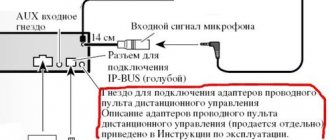
here is the radio pinout sent by a kind Chinese
we are interested in the key1 and key2 wires
Depending on the type of buttons, the connection varies. in the case of an outback, it is connected like this: key1 and key2 are twisted together. further in the standard wiring we look for this connector
There are two wires responsible for the buttons: lilac/white and orange/white. Since the buttons are resistive (each button has its own resistance), we connect one of the wires to ground (I connected it to the negative wire of the radio), and the second wire to key1 and key2 twisted together. we isolate everything well and enjoy))) the buttons are configured in the “buttons on the steering wheel” program, using it you can assign two functions to one button (short press and long press)
Adapter for connecting multifunction steering wheel
In order for the buttons on the steering wheel to start working on the Android radio, you need to make a special adapter and connect it according to the following diagram:
- The dotted line highlights the part that is added to replace the standard MMC.
- The dotted line on the outside is the standard layout, which remains unchanged.
We connect the Android radio through the adapter we made. All that remains is to train the buttons on the steering wheel in the radio settings.
Advantages and disadvantages of the steering wheel remote control
The main advantage is the increased ease of control of the head unit. You can perform various operations with the radio without taking your hands off the steering wheel. You can place buttons on it that are responsible for accessing frequently used functions of the car radio, such as adjusting the volume, tuning radio stations and switching music tracks.
If there is no room to place buttons on the steering wheel, the steering wheel joystick for radio control can solve this problem. It offers the same ease of use, and the connection to the radio is more reliable thanks to the direct connection. Unlike a joystick, a steering wheel with a remote control is connected using slip rings or a harness, which has a limited lifespan due to constant bending or friction. This is the only drawback of this accessory.
How to connect a rear view camera
The standard multimedia system, when reverse gear is engaged, supplies a camera supply voltage of 6.2 V to pin C7 (mini-ISO connector). And the Mekede radio on Android only receives 12 volts to pin 6 (section K) and does not supply the power supply voltage for the camera. To connect a 6V camera, you will have to make a voltage level converter using a 7805C stabilizer and two 1N4148 diodes. As a result, a voltage of 6.6 V is formed at the output of the converter. You can also get by with one 6 V stabilizer 7806 (KR142EN5B) without using two additional diodes.
Instructions
Connecting and installing the steering remote control for the radio can be done at home. First you need to disconnect the battery. Then the standard steering wheel and head unit are removed. The further procedure depends on the installation and connection method.
How to install
To install the radio control panel on the steering wheel, you will need to remove the trim and the horn button from it. In their place, universal buttons with an adapter are installed and secured. If a harness is used for connection, it is secured to the steering wheel and its column with clamps. The steering column switch can be installed on the housing next to the ignition switch and the windshield wiper lever. All wires are laid under the dashboard, and the radio is installed in its place.
How to connect
If the remote control for the radio is connected to the steering wheel via a minijack, then you should insert the plug into the socket for the remote control. Power to the multifunction steering wheel module is supplied from the blue and white stripe wire of the car radio. To connect the buttons on the steering wheel to the head unit via the CAN bus, you must insert the plug into the appropriate connector. The car radio and ignition are then turned on to activate communication between the two devices.
The connection can also be made through the ISO connector, since some manufacturers provide unused contacts in such a connector, to which an adapter for a car radio with a steering wheel remote control is connected. After connecting the control device, you should check its functionality.
How to use
If the radio steering column control switch or multifunction steering wheel is configured, then the keys on them should perform the same functions as on the front panel. Otherwise, you will need to learn the buttons on the steering wheel. In most cases, this is done using the universal remote control included with the car radio. To enter the learning mode, the adapter wire responsible for this function is connected to ground or the positive pole. After this, the corresponding LED should light up. If there is a buzzer, it will emit a confirmation signal.
Then you should press and hold the radio control button on the steering wheel for several seconds, for which you need to assign a function, for example, increase the volume. The assignment mode indicator will light up. After this, you should press a similar key on the hand-held control panel of the head unit. The LED indicating the purpose should go out. The buzzer will sound a different tone.
The remaining buttons on the multifunction steering wheel are programmed in the same way. After completing the setup, you must de-energize the terminal responsible for this mode in order to start using the steering control device. It is worth considering that the connection process for working with Chinese radios may differ.
Connection methods
- If the radio comes with a remote control (remote control), then the connection can be made through the minijack connector, activating the multifunction buttons and supplying power using two wires from the device directly: brown and red-blue.
The 3.5 minijack connector is connected to the remote control into a standard socket. - To connect via the CAN bus, the programmable adapter is connected to the radio via an ICO adapter and output to the multifunction steering wheel.
What could be on the steering wheel?
On our roads you can find vehicles of various classes; naturally, the electronic components of such cars will be significantly different. Multifunctional steering wheels will also differ depending on the class. So, for example, in an inexpensive car, at best the steering wheel will control the audio system, and even then only the function of turning it on or off. Sound adjustments and other settings will most likely have to be made as usual.
If the car is of a slightly higher class, then the steering wheel will most likely also have controls for adjusting the climate system, controlling the on-board computer and cruise control.
In even more advanced versions, you can find the ability to control a mobile phone from the steering wheel. This feature is called “hands free” or “hands free”. Today, many smartphones have the ability to access car audio systems, and by controlling the smartphone from the steering wheel, you can also control the multimedia system.
In addition to the listed functions, the multifunction steering wheel buttons can control:
- Operation of manual and automatic transmissions.
- Monitoring transmission functions in vehicles with all-wheel drive.
- Adjusting the operating modes of the suspensions, which changes the ground clearance and their rigidity.
Connection errors
Typical malfunctions in the operation of multifunction steering wheel buttons occur for the following reasons:
- Incorrect pinout of connections - connect according to the diagram.
- The contact on any connector is broken, or a wire break has occurred: if you cannot visually find a break, then you need to “ring” sections of the wires with a multimeter in ohmmeter mode and check the connections at the terminals.
- One of the functions of the button does not work - the activation was not complete: reset the multifunction steering wheel settings by disconnecting the adapter, and reprogram the system again.
- Spontaneous failure of operation - short circuit (fuse has blown): replace the fuse in the block, check the connectors for moisture, dirt, inspect the fastening of the ground wire.
During installation, you should take into account the standard connectors of a particular radio - connection diagrams may differ: in such cases, you should adhere to the technical description of the multimedia device.
- Connecting a car radio with your own hands
Even today, in a top-spec car, you can see a boring head unit with a minimal set of functions.
It is quite logical that many car owners, immediately after purchasing a new car, replace the factory radio with advanced infotainment systems running on the popular Android operating system.
There are usually no issues with the installation of such 2-din systems, since they fit neatly into a standard mounting location and are connected according to a standard scheme, but not everyone can handle setting up the controls.
This article is intended to help you understand the designation of the Android radio buttons and their correct configuration for easy use.
What is needed to connect the multifunction steering wheel to an aftermarket radio?
Steering wheel tuning involves installing ready-made sets of service buttons for a specific car brand - in this case, connecting functions is simple: each set comes with an adapter that is compatible with the main electrical equipment. Non-standard solutions require a special device with a programmer and compliance with the “pinout” of connectors.
Adapter
The adapter type ACV SWI-1 is universal, capable of programming multifunction steering wheel functions and combining any non-standard radio according to a standard scheme. To install it in the control circuit, you will need another ICO adapter.
Attention! Before installation, disconnect the battery by removing the minus terminal.
Using arduino in a car - controlling the radio using buttons on the steering wheel
When I decided to change the radio in my car, I was faced with a choice: to lose the standard sound control using the buttons on the steering wheel, or to buy a special (quite expensive) adapter. Then I thought, why not make such an adapter myself? A review for those who are familiar with a soldering iron. First, the essence of the problem. Many cars have a standard radio control installed on the steering wheel. These buttons work on the principle of a resistive keyboard, which allows you to transmit a signal through just two wires. For example, we press the volume up button - a resistance of 130 Ohms appears in the circuit. We press volume down - a resistance of 240 Ohms appears, etc.
Many modern radios also have the ability to connect a wired remote control. But the problem is that the standards of all car and car radio manufacturers are different. For example, with Pioneer radios, to increase the volume, you need to “apply” a resistance of 16 kOhm.
Therefore, between the steering wheel and the radio, you need a special adapter that will convert the resistance values into understandable values for the radio.
When I looked for such an adapter for my car, it turned out that it costs more than $50. Considering that I got the radio itself for a ridiculous $30-35, I decided to try to make an adapter myself using an Arduino. At that time there was no ready-made scheme on the Internet; I had to invent it myself.
I would like to apologize in advance for possible inaccuracies and errors - I am not well versed in electronics. I collected all the information bit by bit from Google. 
In my project I used the following components: 1. Suzuki Swift car 2. Pioneer MVH-X165UI car radio (bought offline) 3. Arduino Nano, maybe Mini (bought on ebay for $2.5) 4. MCP4131, 100k digital potentiometer (bought offline for $1, for some reason on ebay they are quite expensive) 5. 10k resistor 6. Development board 7. Step down buck converter for $1.5 to make 5V from 12V
The principle is simple - at the input we measure the resistance from the buttons on the steering wheel. If the resistance corresponds to pressing a button, then at the output potentiometer we set the corresponding resistance required by the radio.
The first thing I did was get a service manual for my car, which shows the resistance values for all the buttons. However, you can simply measure them with a multimeter.
Also found on the network is the following diagram of a wired remote control for a Pioneer radio (uses a 3.5mm plug):
I don’t have Preset Up/Down buttons on the steering wheel, so I used only two contacts on the plug - Tip and Sleeve.
Because The range of resistances required by the radio tape recorder is from 1K to 62K, then I bought the MCP4131 microcircuit - this is a 100K digital potentiometer with 129 adjustment steps. 129 steps are enough, because... We don’t need super accuracy; the radio understands resistance with a spread of somewhere around 10-20%. Well, you don’t have to buy the MCP4131, I think any other digipot with similar characteristics will do.
There are instructions on the Internet for using a digital potentiometer with an Arduino, I liked this video, it’s very detailed and accessible.
I will not explain the basics of working with Arduino; there are a lot of other specialized resources where everything is described much better.
The connection diagram looks like this:
Resistance is measured at pin A5 using a voltage divider with a 10K resistor.
The potentiometer is connected according to the following diagram:
4, 7 — GND 8 — +5V 1 — arduino pin 4 (you can choose another) 2 — arduino pin 13 3 — arduino pin 11 6 — to the radio, “Tip” contact on the plug
Sketch under spoiler
#include // the SPI library should be in the standard software, or you can download it. // Codes of the buttons on the steering wheel const int VOL_UP=1; const int VOL_DN=2; const int PREV_TR=3; const int NEXT_TR=4; const int MODE=5; const int MUTE=6; int csPin=4; // CS on the digital potentiometer int wheelPin=A5; // analog pin on which we read the resistance of the button pressed on the steering wheel int i=0; int prevButton=0; void setup() { pinMode(csPin, OUTPUT); delay(50); SPI.begin(); delay(50); SPI.transfer(0); // command SPI.transfer(0); // value pinMode(wheelPin, INPUT); delay(100); //Serial.begin(9600); } int getR() { // This function reads the resistance from the buttons on the steering wheel and returns the code of the button pressed, or 0 // read the resistance (actually the voltage, of course) on the analog pin int r=analogRead(wheelPin); //Serial.println®; // We are looking for which button corresponds to this resistance. // These resistance values are suitable for Suzuki Swift; for other cars the numbers will be different. if (r>=9 && r<=15) return(VOL_UP); if (r>=18 && r<=26) return(VOL_DN); if (r>=120 && r<=156) return(PREV_TR); if (r>=60 && r<=80) return(NEXT_TR); if (r>=33 && r<=47) return(MODE); if (r>=2 && r<=6) return(MUTE); // if no button is pressed, return 0 return (0); } // MAIN LOOP void loop() { int currButton=getR(); // enter the code of the pressed button into the currButton variable if (currButton!=prevButton) { // if the value has changed since last time delay(10); currButton=getR(); // wait 10ms and read again to eliminate the button “bouncing” if (currButton!=prevButton) { // if the button code has definitely changed since last time //Serial.println(currButton); prevButton=currButton; // save the new value to the prevButton variable // Set the resistance on the potentiometer, thereby sending a command to the radio. // Resistance values are given for Pioneer; for radios of other brands the numbers will be different. SPI.transfer(0); switch(currButton) { case VOL_UP: SPI.transfer(21); break; // 16k case VOL_DN: SPI.transfer(31); break; // 24k case PREV_TR: SPI.transfer(14); break; // 11k case NEXT_TR: SPI.transfer(10); break; // 8k case MODE: SPI.transfer(2); break; // 1.6k case MUTE: SPI.transfer(4); break; // 3k default: SPI.transfer(0); break; // 0k } } } delay(5); }
Photo of the finished board.
The photographs on the reverse side were not preserved, because... this was a year ago and I had no plans to write a review. Well, there’s nothing interesting there - a bunch of jumpers and bad soldering
The Arduino can operate from 12V, but I decided to install a step-down converter to 5V. Firstly, I powered the DVR from it, thereby freeing up the cigarette lighter socket. Secondly, I read that the voltage in the car network is dirty and unstable, it can fluctuate by several volts, both down and up. The converter will withstand such surges, but the arduino may burn out. To further “clean” the power supply, I added several protective elements - a diode, a zener diode, a capacitor. I looked at the diagram here. I have some doubts about its necessity, but I decided - let it be.
That's all. The device has been working normally in the car for about a year now. And I saved some money and gained valuable experience.
Multifunctional steering wheel
The name multifunction steering wheel is an abbreviation for the generally accepted term - multifunctional steering wheel. What is hidden under this designation?
As mentioned earlier, all automobile designers strive to make driving a car very convenient. Since modern vehicles have many different gadgets and bells and whistles, which often require switching and adjustments during a trip, the driver has to be regularly distracted by them, which in turn can lead to emergency situations. It was this factor that was decisive for auto engineers in creating a multifunctional steering wheel. They tried to transfer some of the control elements to the steering wheel and save the driver from having to throw the steering wheel and switch all sorts of buttons and levers.
Multifunction steering wheel (multifunctional steering wheel) is a regular steering wheel on which various auxiliary elements for controlling the electrical equipment of the car are located. In modern cars this can be a very advanced technological device.