Cars admin26.02.2020
Hello dear subscribers and guests!
Today I want to talk about my method of connecting electric mirrors with grants in the “Lux” configuration.
I also want to talk about connecting the power window control module from the viburnum. I chose this particular unit because it has power window lifter buttons. I also did not plan to install power windows on the rear doors in the future. Of course, I wanted to install a unit with a “Lux” grant, but the unit is completely electronic. It is controlled via the CAN bus and the body electronics control unit. In short, there would be too many hemorrhoids with the installation of such a block.
So, let's take a closer look at what we need to install and connect such an ESP control unit:
1. The ESP block itself is from viburnum. The original number of such a block is 11183-3709810.
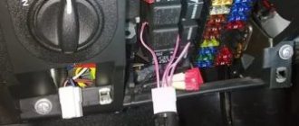
2. Connector for power windows in this unit. It looks like this:
It is very difficult to find. I miraculously found a similar connector at the local market. Since it is rare, they charged me 300 rubles for it. In principle, if you couldn’t find it, you can connect it without this connector using regular terminals.
3. Connector for connecting the central locking switch (CL).
A connector from the ESP is suitable, which will need to be removed from the standard wiring.
4. Connector for connecting electric mirrors to the joystick.
I never found him. To connect I used wires with connectors from an old computer. Similar single connectors are used to connect the power button, reset button, etc.
You need eight pieces. I glued them together with super glue and heat-shrink them. The result is a connector like this:
5. Reciprocal connector for connecting electric mirrors.
I didn't find it either. I got out of it very easily. I bought two connectors for six terminals (male, female) and the terminals themselves for crimping.
6. Wires with a cross section of 1-1.5 square meters.
Preferably multi-colored.
All you need is 5 pieces of different colors, each 5 meters long. Now that you have prepared everything, let's move on to action.
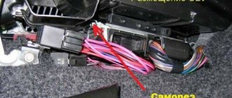
1. Remove the door trims. 2. Remove the center console. 3. Remove the instrument cluster. 4. Remove the glove compartment (glove compartment). 5. We lay five wires in the right passenger door. Exactly five, because it’s better to take the mass on the body.
It’s not in the right door, and it’s not comme il faut to take the mass through the hinges))). How to route wires through the door connector can be found on the Internet, or look in my blog here.
6. Connect the ground wire under the glove compartment in a place convenient for you. 7. We pull 4 wires for controlling electric mirrors through the entire panel into the left driver's door. We make a loop on one wire to connect the heated mirrors. We bring this loop to the heated rear window button. 8. There is no need to pull the weight into the driver's door. There it is on the solder of black wires, it is easy to find. So we put exactly 4 wires into the driver's door. 9. Below I post tables that detail the connection of the standard wiring of the “Norma” grant to the ESP Kalina block. On the left is the contact number in the connector. On the right is the color of the wire that needs to be connected to this contact + the pinout of this wire and contact.
Reasons for failure
The window regulator consists of mechanics and electrics, and therefore the reasons must be sought in these parts. Let's look at where the problem may lie:
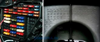
- A fuse has blown or a relay has broken.
The relay can be replaced with a jumper as in the photo. But remember that this is a temporary option, be sure to change the relay in case of breakdown
Tap to the left of the button, then try pressing the button. If it works, then the contact between the wire and the button is to blame.
All these reasons can lead to the fact that one or both window regulators may not work.
Troubleshooting Methods
So, when the window regulator stops working, it is necessary to find and eliminate the cause. Let's look at the whole process and steps step by step:
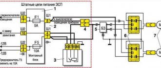
- The first thing you need to pay attention to is the fuse . In the block it is marked as F5. You need to take it out and look. If it burns out, it should be replaced with the same one with the appropriate marking.
- If the fuse is intact, then the problem is in the power supply and you need to look for a broken wire problem . We take out the fuse and use a tester to check whether there is voltage in the on-board circuit. To do this, you need to insert the probes into the sockets and see if there is power supply. If not, then you should check the wires, relays, and control unit.
Vehicle Maintenance
Using 2 small flathead screwdrivers, you need to remove the block from the grooves. Direct replacement is carried out without sudden movements, so as not to break fragile elements. As soon as it becomes possible to get to the wiring, you need to get rid of the plug with equal care. This can be done with little physical effort. A latch is used to disconnect the second plug.
After the glass power supply is removed, it must be inspected. The presence of any mechanical damage indicates the need for mandatory replacement. Even in-depth repairs will not help restore its functionality. Before installing a new unit, another check must be carried out. Its relevance increases when it comes to replacing a relay.
After removing the faulty part, you should manually check all connecting fasteners and wires. Traces of charring or damage are a sign that the Kalina power window button most likely needs to be replaced. If this is not done, then the need for repeated repairs will arise within 2-3 months. This is due to the increased load on the Lada window regulator.
Installation of a working unit occurs strictly in the reverse order. First, carefully connect the wires and 2 plugs. If the window lift button has been manipulated in any way, the reliability of its fixation must be checked manually. If a visual inspection does not reveal any problems, then the Kalina window lifter button is placed in its place.
Once all the wires are connected, the unit is secured using the provided latches. The repair is completed by checking the efficiency of the system.
You need to pay attention to the smoothness of the ride and the absence of the slightest delays. In the future, if the window regulator on Kalina does not work, you can fix the problem yourself
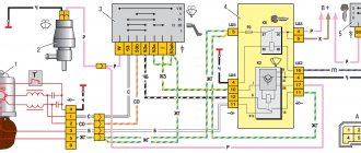
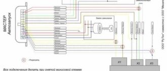
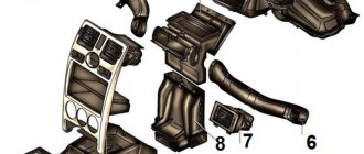
Let's look at the diagram for switching on power windows on the Lada Kalina
Diagram (click to enlarge)
The decoding of the notation looks like this:
2 — ignition switch;
3 — power window switch for the right front door;
4 — power window switch for the right rear door;
5 — gear motor for the power window of the right front door;
6 — gear motor for the electric window of the right rear door;
7 — gear motor for the electric window of the left rear door;
8 — gear motor for the electric window of the left front door;
9 — left rear door power window switch;
10 — left front door power window switch;
11 — relay for turning on electric windows;
A - to power supplies;
B - to the instrument lighting switch;
C - the order of conditional numbering of plugs in the power window blocks.
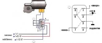
Is it the motor or the mechanics that is at fault?
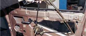
If everything in the electrical part is functional, then it is necessary to look for the cause in the mechanical part. To do this, you will have to dismantle and diagnose the window regulator. Let's look at how to remove this node:
- We dismantle the door card.
Door card removed
It is worth inspecting the removed window regulator for damage.
Removing the window motor
The most common malfunction is wear of the roller teeth or breakage of the traction cable. These parts need to be replaced, but often the entire mechanical part of the window regulator is replaced.
Diagnostics of the window lifter trapezoid
conclusions
Thus, it can be seen that the reasons for the malfunction of the window regulator are quite simple to eliminate. If you find the reason, you can easily repair the unit yourself. On the Lada Kalina there are only a few reasons why the window regulator fails.
Anonymous:
guys, this is wrong, open the keys on the door and look at the fit of the plates when the button is turned on
Vladimir:
I had such a situation, I contacted repairmen. But after reading the article, it seems to me that I would have solved the problem myself. Thank you.
Alexander :
All descriptions are stupid. We need to be simpler. Usually stops working in the closed position. A common cause is clogged glass seals. You need to turn on the ignition and interior lighting. We press the window lowering button, at this moment the interior lamp should dim slightly. If yes, the electrical is fine, look for the cause in the mechanics. If it doesn't go dark, the reason is electrical, start by checking the fuse and beyond. According to mechanics, insert some card from the outside of the glass into the seal and move it in a circle, pouring water. If it doesn’t work after that, open the door, one presses the lowering button, and the other hits the glass with two palms on both sides of the glass simultaneously downwards, if after several attempts did not work - disassemble the door trim, loosen the electrical fastening bolts. engine window regulator and press the button. If it works, run it several times and tighten the bolts back. If not, replace or repair the window regulator.
Albert:
That’s exactly how I cured it by disassembling and lubricating the mechanisms!
Source
Window lifter.RF › Blog › Connecting the MAX-2 electric window controller on LADA Kalina
We continue to demonstrate the connection of the MAX-2 window lift module, which is not just a window closer, but a full-fledged window lift comfort unit.
In this video we will show the connection process on LADA Kalina I (VAZ-1117, -1118, -1119).
Brief content of the video: – How to prepare the MAX-2 controller for connection. – How to install in the door and connect the controller to the power windows and on-board network. – How to “train” the MAX-2 controller.
For more information about the functions of MAKS-2, see our other videos: - general overview - demonstration of functions
You can also see instructions for installing MAX-2 on other cars: - LADA 110 - LADA Samara
If you liked our video, click “like” and share with your friends. And also subscribe to our page - it will be even more interesting)
Buy the MAKS-2 module in the Steklopodem.RF online store
Comments 29
I don’t understand how where, how to connect the wires, you showed the final result of twisting the wires, when the wire is cut off, what to do with the plus minus and the white wire at the exit of the block, the input is clear plus and minus separately, you can be more detailed
The kit includes a connection diagram. I recommend doing your research before watching the video. Then it will be clearer what, why and why.
Hello! I installed this module. From the signaling I found a wire that is responsible specifically for the window closer, checked it with a tester, when the car is disarmed there is a “+” on this wire, when I arm the “+” it disappears, I connected this wire to the yellow wire, the closer does not work. I decided to experiment, connected it to the black wire, the door closer works but only works in reverse, when disarmed it raises the windows and blocks the buttons. Any thoughts on what could be wrong?
>From the signaling system I found a wire that is responsible specifically for the window closer, checked it with a tester, when the car is disarmed there is a “+” on this wire, when I arm the “+” it disappears, This means that the pulse at the alarm output is negative.
>connected this wire to the yellow wire, the closer does not work. I decided to experiment, connected it to the black wire, the closer works. This is how it should be: the negative control pulse is connected to the black wire of MAX-2.
Similar products
Do you like the store? Rate it on the Market!
Familyevich Evgen
Very good store, I recommend it!
Aminev Maxim
The best window lift store in Russia! :)
Latysheva Julia
Fast? placing and sending an order, complete and accurate information about the order.
Osipov Alexey
They called back right away and clarified the order. The order arrived ahead of schedule.
Safarov Oleg
Well done. You work quickly. And most importantly, the prices are reasonable. Keep it up!!
Nikolay Sotnichenko
Advantages:
Good order processing speed. Pleasant communication from employees.
Disadvantages:
none.
ESP VAZ button pinout
There are 2 types of Kalinovsky ESP keys: low-current (multiplex) and power.
To install low-current ESP keys, you will need to install an electrical package control module/electric package controller (2170-3763040).
This will also allow you to close the doors and windows of the car with a key or key fob, there will be a two-stage door opening, and the ability to control electric mirrors and door locks from the glass lift module.
If you use ESP power keys, then everything is simpler; no additional control units are required. You just need to connect the keys correctly.
Remember the main thing: power keys are produced by Avar, and multiplex keys are produced by Itelma.
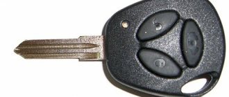
It is necessary to purchase an ESP key for a VAZ 1118, sample AVAR 1118-3709613-10 (921.3709). It has power contacts, the socket of which exactly fits the 10.
Their cost is about 30 - 50 hryvnia.
It will not be possible to install 1118-3763080 - a new module with 4 ESP keys, central locking (CL) and mirror adjustment, since they are all multiplex. And this is reasonable, since it is difficult to stretch such a mass of power wires through the door.
Connection diagram for ESP module for Kalina buttons and pinout
connection diagram for the Kalinamotor ESP module in the driver's door
- mass (only 1 can be combined inside)
- +12V for driver's window
- weight
- +12V for passenger window
- absent
- socket module ESP viburnum dimensions
- to the 3rd leg of the key in the passenger door
- to the 6th leg of the key in the passenger door
- Central lock key:
- socket of central locking module ESP Kalina closing
- weight
- absent
- dimensions
- backlight weight
- absent
- opening
You can purchase the Kalinovsky module and ESP control keys in online stores, and if you modify the VAZ-1118 control module with electric window lifts, you can install 4 keys. You will simply need to connect the module 1118-3709810-10 with 2 piece keys 2170-3763040. So, the ESP power module of 4 keys and central locking is ready!
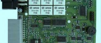
The electrical package control unit (pictured below) Kalina Lux does not work. Or rather, it does not respond to my presses. It is illuminated, when I press the buttons, click, I hear a single short sound in the area of the speedometer/heater (you can hear it in the video below). This thing appeared in the morning, I walked away for an hour, everything worked. By evening everything stopped responding again and it’s been like this for the whole day. Neither the central locking, nor the mirrors, nor the power windows respond to my presses.. What's the matter? I disconnected the terminal for 15 minutes, it didn’t help, the alarm was starline.
How to determine why the window regulator does not work
1. In the mounting block, check the power window fuse (F2, 25A) and relay (K2).
2. Remove the door trim and check the voltage at the power window motor terminals using a multimeter or a 12V test lamp.
If there is no voltage, then check the serviceability:
- power window buttons
- wiring (connector connection)
- electrical package control unit (central body electronics unit or CBKE), which is used in the “luxury” configuration.
If current flows to the electric motor, but the glass does not move, then we check:
- malfunction of the window lift motor (for example, the drive motor brushes are stuck/sticking, the plastic gear in the gearbox is worn out)
- The window lift cable is frayed
- glass is jammed (distorted)
The most common problems with power windows are:
- Window lift motor malfunction.
- Skewed, broken power window cable.
- Poor contact.
Let us remind you that on the website you can find solutions to other problems in the operation of the Lada Kalina 2, for example, squeaking clutch pedals.
Kalina ESP buttons on VAZ 2110
There are two types of Kalinovsky ESP buttons: low-current (multiplex) and power. To install low-current ESP buttons, you will need to install an electrical package control unit/electrical package controller (2170-3763040). This will also allow you to close the doors and windows of the car with the key (the control is built into the key), there will be a two-stage door opening, and the ability to control electric mirrors and door locks from the power window unit. In the case of ESP power buttons, everything is much simpler, no additional control units are required. You just need to connect the buttons correctly.
Remember the main thing: power buttons are produced by Avar, and multiplex buttons are produced by Itelma.
Installation of Kalina power window buttons on a VAZ 2110
Installation of the Kalina window lifter unit on a VAZ 2110
And there are power units, but only with 2 ESP and central locking buttons (for example, 1118-3709810-10 (351.3769)). You can buy one for 600 rubles. Wiring diagram for the Kalina ESP unit and pinout: Main connector:
- motor in driver's door
Lada 2112 with parts of Priora 2. › Logbook › Connecting ESP buttons from Kalina…
Hello everyone) In general, I ordered door trims from Priora 2. and because. Each trim has a plastic insert with an ESP button, so I had to figure out how to get my own button in each door. At first I thought about stupidly extending the wires and there would be a button in each door, I will also have one in the driver’s room. But then, I was surfing around in the drive and came across a wiring diagram for the ESP unit from the viburnum. The unit includes mirror adjustment, central locking and front window buttons. Well, let’s say there will be 2 front ones, but what should we do with the rear ones?)) A block with 4 buttons is not suitable. Neither Priorovsky, nor Kalinovsky. There are rumors that to connect the unit you need a power unit, then register it in the brain and a lot of other things. This is definitely not my option)) So, give it a collective farm! What is the collective farm? The fact is that you will have to do a lot of cutting, shredding, sawing, biting, etc... But first, let's go shopping)) 1.
We buy
4 plastic inserts for the doors
(each door has its own, respectively).
2.
We buy
a control unit
(stuffed) from
viburnum
(
Catalogue number 352.3769
).
3.
Then
single ESP buttons
from
“Kalina”
or
“Grants”
.
Or 3 single pieces ( 21900-3709810
) and a control unit from Grants (21900-3709810-00).
This is a relatively easy path. Or all 5 single buttons. 4. Block with wires from the ESP control unit. 5. Block with power window switch wires. 6. Wires with a cross section of 0.5 mm - 10 m - 7 twists.
(at the canopy in the area it is sold in twists).
7. Wires with a cross section of 0.5 mm - 5 m - 1 twist.
(or combine points 6 and 7 and buy 75 meters of wire).
8. Female terminals with double-sided wires (8 pieces)
(I have no idea what they are called, but on both ends of the wire there are female terminals in a plastic block).
Sold in radio equipment. 9. Block with terminals mother tsz.
driver's door - I just took 6.3 mm female wires -2 pieces and crimped each wire. After all this we run home. Look at the diagrams and twist the wires.
Connection instructions
It should be borne in mind that installing rear window regulators or front devices is a rather labor-intensive task. Before you begin the process, weigh all your strengths. You need to know not only how to install window closers and electric motors themselves, but also how to adjust, configure and train the system. Not every car enthusiast can do this at home. Detailed instructions on how to connect power windows are presented below (the author of the video is the irtimidneuss channel).
Stages
Installing universal electronic devices first of all implies familiarity with the circuit. The wiring diagram for the power windows should be included in the kit. Before starting the process, disconnect the battery.
How to install and connect power windows correctly:
- First, remove the door cards - to do this, unscrew all the bolts, remove the handles and disconnect the trim clips.
- The glass must be securely fastened before dismantling the old mechanism. The glass needs to be secured with tape. Also remove all rubber plugs from the service holes through which the wires will pass.
- Install the adjusting plate into the inclined groove and secure it; for this you will need M6 bolts. The plate is attached to the glass bracket, be careful not to damage it.
- The ESP mechanism must be installed in the upper hole in assembled form. You need to securely mount the device to the door, for this you will also need M6 bolts with lock washers. As a rule, installing an electronic device involves the use of three bolts, but their number may vary depending on the design of the device.
- The next step is to remove the two plastic plugs located in the front panel; to do this, you will need to disconnect the wire from the cigarette lighter device in advance. Then simply pull the wire - it can be put through the technological hole that is located in the car door, as well as its pillars. At this stage, be careful - when laying, make sure that the wires do not come into contact with the moving elements of the electronic device, otherwise the wiring may break. If necessary, all wires will need to be secured with electrical tape, and they will also need to be additionally wrapped with it.
- Next, you need to make sure that you have connected the contacts to the switch correctly. Connect them to power and turn on the side lights. In this case, the backlight of the ES button should be activated. If it does not light up, then try swapping the contacts.
- Now we need to work on the lever system. Connect the device to the plate and glass. Tighten all nuts securely as they may become loose while driving. You need to adjust the device so that the glass is in one position and securely fastened.
- Next, the adjusted window regulator should be connected to the power supply, that is, the on-board network of the car. To avoid mistakes at this stage, you should study the car's wiring diagram, as well as the ED diagram.
- After all these steps are completed, you need to secure the clamps. For example, you can use silicone spray for this (the author of the video is LESH MASTER).
Electrical equipment Lada Kalina
KALINA
repair
electrical equipment
Car electrical diagram
Diagnostics of electrical equipment of VAZ 1117 Kalina. VAZ 1118 Kalina car diagrams, wiring, electric motors VAZ 1119 Lada Kalina.
Electrical circuit diagram of a car Repair of components of the electrical circuit diagram Lada Kalina do-it-yourself repair Lada electrical equipment, design and maintenance
Electrical diagram of a Lada Kalina car: 1 - right headlight; 2 — hood open sensor; 3 — sound signal; 4 - starter; 5 - battery; 6 - generator; 7 — windshield wiper gear motor; 8 — left headlight; 9 — right front door power window switch; 10 — motor-reducer for window lifter of the right front door; 11 — connection blocks to the right front speaker; 12 — electric drive for locking the lock of the right front door; 13 — windshield washer electric motor; 14 — ambient temperature sensor; 15 — block for connecting the wiring harness of the engine control system; 16 — electric drive for locking the left front door lock; 17 — brake fluid level sensor; 18 — connection blocks to the left front speaker; 19 — power window switch for the right front door, located on the driver’s door; 20 — left front door power window switch; 21 — door lock switch; 22 — motor-reducer for window lifter of the right front door; 23 — mounting block; 24 — control unit for the automobile anti-theft system; 25 — security alarm control unit; 26 — instrument cluster; 27 — right side turn signal; 28 — glove box lighting lamp; 29 — switch for the glove compartment lighting lamp; 30 — brake signal switch; 31 — ignition switch with transponder of the automobile anti-theft system; 32 — control unit for external lighting, instrument lighting and headlight beam direction control; 33 — steering column switch; 34 — left side direction indicator; 35 — connection blocks to the right rear speaker; 36 — electric drive for locking the right rear door; 37 — rear window heating switch; 38 — reverse lock switch; 39 — alarm switch; 40 — heater fan operating mode switch; 41 — additional resistor of the heater fan electric motor; 42 — heater fan electric motor; 43 — connection blocks to the left rear speaker; 44 — electric drive for locking the left rear door; 45 — electric fuel pump with fuel level indicator sensor; 46 — reverse light switch; 47 — parking brake warning switch; 48 — cigarette lighter; 49 — reverse lock solenoid; 50 — connection blocks to the head unit of the sound reproduction system; 51 — backlight lamps for the ventilation and heating system control unit; 52 — electric power steering control unit; 53 — interior lamp; 54 — right rear light; 55 — electric drive for locking the trunk lock; 56 — trunk light switch, built into the trunk lid lock; 57 — license plate lights; 58 - additional brake signal; 59 — rear window heating element; 60 — trunk light; 61 - left rear light. This diagram does not show the connection points and wiring harness terminals.
Electrical equipment Lada Kalina
Components of the Lada Kalina car
Maintenance and operation manual for Lada Kalina, with injection engines 1.4 and 1.6. The car owner can easily diagnose and repair the Lada Kalina car unit on his own in a garage workshop, find faults in electrical equipment, steering, brake system, engine and gearbox. Care tips can also be found in our sections. All Lada Kalina manuals are divided into thematic sections.
Wiring diagrams Lada Kalina 2 hatchback (luxury)
| This section contains electrical diagrams for the new Kalina (VAZ 2192) luxury version. |
Front wiring diagram Kalina 2
How to change the heater fan in a Lada Kalina car yourself
1 – right headlight; 2 – electric motor for washers; 3 – left headlight; 4 – starter; 5 – rechargeable battery; 6 – main fuse block; 7 – generator; 8 – sound signal; 9, 10, 11 – front wiring harness blocks to the instrument panel wiring harness blocks; 12 – air conditioning fan electric motor; 13 – electric fan of the engine cooling system; 14 – ABS hydraulic unit; 15 – right front speed sensor; 16 – left front speed sensor; 17 – front wiring harness block to rear wiring harness block; 18 – right fog lamp; 19 – left fog lamp; 20 – ambient temperature sensor; 21 – reverse lamp switch; 22 – air conditioning compressor; 23 – audible alarm signal; 24 – rear window washer electric motor.
Instrument panel diagram Kalina 2
1,2 – blocks of the instrument panel wiring harness to the blocks of the front wiring harness; 3, 4 — blocks of the instrument panel wiring harness to the blocks of the rear wiring harness; 5 – lighting control module; 6 – ignition switch; 7 – on-board computer mode switch; 8 – windshield wiper switch; 9 – instrument cluster; 10 – light signaling switch; 11 – trunk lock drive switch; 12 – diagnostic block; 13 – block of the instrument panel wiring harness to the block of the wiring harness of the air supply box; 14 – rear window heating switch; 15 – alarm switch; 16 – brake signal switch; 17 – multimedia system; 19 – rotating device; 20 – driver airbag module; 21 – sound signal switch; 22 – mounting block: K1 – relay for the electric fan of the engine cooling system; K2 – door lock relay; K3 – additional starter relay; K4 – additional relay; K6 – windshield wiper relay; K7 – headlight high beam relay; K8 – sound signal relay; K9 – relay for low beam headlights; K10 – relay for turning on the heated rear window; K11 – main relay; K12 – fuel pump relay; 23 – electric power steering; 24 – cigarette lighter; 25 – lampshade lighting of the glove box; 26 – glove box lighting switch; 27 – block of the instrument panel wiring harness to the block of the ignition system wiring harness; 28 – engine control system controller; 29 – block of the instrument panel wiring harness to the block of the rear wiring harness 4; 30 – electronic accelerator pedal; 31 – additional resistor; 32 – heater electric motor; 33 – solar radiation sensor; 35 – relay (K13) of the electric fan of the engine cooling system 3; 36 – compressor relay (K16); 37 – relay (K14) for heating the windshield; 38 – relay (K15) for heating the windshield 2; 39 – headlight range control regulator; 40 – clutch pedal position signal switch; 41 – passenger airbag module; 42 – evaporator temperature sensor; 44 – windshield heating element; 46 – windshield heating switch; 47 – central unit of body electronics; 48 – micromotor reducer of the air flow distributor damper; 50 – controller of the automatic climate control system; 51 – micromotor gearbox for mixing air flows; 52 – micromotor gearbox for recirculation damper drive.
All other schemes are suitable for the “norm” and “standard” configurations.
Window control unit Kalina
Sometimes, during the run-in phase of the car, the power window control unit begins to malfunction; Kalina is no exception in this case. Often such a block simply refuses to move the rear or front windows in space. There are many reasons for this. The most common are assembly defects and operating errors. In any of these cases, you can independently diagnose Kalina's power windows.
Return to contents
Analysis of the current situation
Drivers with basic skills in working with tools will understand what needs to be done if the power window on a Kalina does not work. First you need to check the installed fuse and relay in the mounting block. The diagram supplied with the official vehicle operating instructions designates the indicated elements as F2 (25 A) and K2, respectively. If the problem could not be detected, then the inspection is transferred to the terminals of the electric motor of the Lada Kalina.
To do this, you need to carefully remove the door trim. A multimeter or a 12 V test lamp will help you find out the exact voltage level. If the terminals show no voltage, you need to check the most likely culprits of a possible malfunction. In the first place is the window lift button, followed by wiring and connectors.
The absence of noticeable signs of malfunction here requires checking the power window control unit. It is important to make one reservation: for a vehicle presented in the luxury configuration, it is necessary to inspect the central body electronics unit (CBEC). The fault diagnosis procedure ends with a conclusion about the passage of current to the electric motor or its absence.
If there is current, but no movement of the Kalina windows is observed, a possible cause should be looked for in the areas described below:
- glass distortion;
- glass clamp;
- the window lift cable is torn or frayed;
- wear of the glass drive motor shield;
- drive motor shield retraction;
Further actions are based on the nature of the identified malfunction. In the worst case scenario, replacing a broken or worn part will take 70 minutes. It all depends on the experience of the car owner and the actual breakdown. For example, removing and installing a new relay will take about an hour.
Return to contents
Vehicle Maintenance
It is recommended to replace any parts in the car only with original ones. Compliance with this requirement will eliminate subsequent unscheduled repairs. If Kalina's power window button requires servicing, then first you will need to find the necessary tools.
Using 2 small flathead screwdrivers, you need to remove the block from the grooves. Direct replacement is carried out without sudden movements, so as not to break fragile elements. As soon as it becomes possible to get to the wiring, you need to get rid of the plug with equal care. This can be done with little physical effort. A latch is used to disconnect the second plug.
And again the power windows)), a jamb on the viburnum
From: Kingdom of Heaven
the same crap, the window lifters on the passenger side (both front and rear) don’t work, the driver’s side are plowing
Posts: 1,754 From: garage
guys, the solution is very simple: if all the components are working, but the lifts still don’t work, do this: knock a couple of times on the door trim approximately at the level at which the motors are located
. Two or three strong blows and everything will work.
I myself encountered the same problem - the lifts did not work, and everything was working. We removed the casing and checked, there is voltage everywhere. We hit the motor with a hammer a couple of times and everything worked. They didn’t even disassemble the second door - I hit the trim a couple of times and that’s it. Kalina has such a problem - the window motors, if you don’t use them constantly, so to speak, “fall asleep.”
Post edited by fourteenth
— May 28 2013, 22:11
Posts: 2,172
guys, the solution is very simple: if all the components are working, but the lifts still don’t work, do this: knock a couple of times on the door trim approximately at the level at which the motors are located
. Two or three strong blows and everything will work.
I myself encountered the same problem - the lifts did not work, and everything was working. We removed the casing and checked, there is voltage everywhere. We hit the motor with a hammer a couple of times and everything worked. They didn’t even disassemble the second door - I hit the trim a couple of times and that’s it. Kalina has such a problem - the window motors, if you don’t use them constantly, so to speak, “fall asleep.”
Posts: 2,172
Most likely, the window regulator is working properly. It’s just that in Kalina it was made somewhat moronic (the cable is stretched in the shape of a figure eight and attached to the glass in two places). Because of this, if the glass is slightly warped, it does not have enough strength to move it from its place, the bimetallic fuse in the motor is triggered and turns off the window regulator for several minutes (until it cools down). You need to remove the door trim, unscrew the window regulator from the glass (in 2 places) and try whether it will drive without glass or not. If it does (which is most likely), you need to adjust the glass (so that it stands without distortion) and screw it to the window regulator. It is also useful to lubricate the rubber bands on which the glass runs with liquid silicone grease. The problem can be radically solved by replacing the window regulator with a rack-and-pinion “Granat”; the original one will periodically fail (this is the design).
From: Kingdom of Heaven
guys, the solution is very simple: if all the components are working, but the lifts still don’t work, do this: knock a couple of times on the door trim approximately at the level at which the motors are located
. Two or three strong blows and everything will work.
I myself encountered the same problem - the lifts did not work, and everything was working. We removed the casing and checked, there is voltage everywhere. We hit the motor with a hammer a couple of times and everything worked. They didn’t even disassemble the second door - I hit the trim a couple of times and that’s it. Kalina has such a problem - the window motors, if you don’t use them constantly, so to speak, “fall asleep.”
I know this feature! I've already beaten him quite a bit, but the problem remains
Source
What is an electrical circuit?
So, an electrical diagram can be understood as a detailed drawing, which reflects in as much detail as possible the placement of all electrical elements in the system, devices and apparatus that ensure its functioning, connections between them, power nodes, connection points, etc.
More on the topic: What are the characteristics of a pit lift?
Control circuits must include a detailed description of such details as the installation method and type of wires, diameter and cross-sectional shape, the number of cores used in their composition, their lengths and widths. In a similar way, the layout of certain elements and materials of layout structures can be described (if they can have any effect on the operation of the device).
All electrical circuits included in the circuit can be divided according to their functional purpose into the following categories:
- power circuits - the main group, which includes switches, fuses, magnetic current coils, contactors, contacts of starters and automatic machines, stator and rotor elements of motors;
Electrical diagram of the lift P 97 MK “Leader”
- control circuits - include elements that provide basic protection of the mechanism from internal and external electrical and mechanical influences. This includes electromagnetic starters, coils and relays. Since we are talking about the installation diagram of a lift, this group should also include regulators for the operation of the lifting boom, limit switches, switches and lift control buttons, starters, contactors and phase control relays.
- auxiliary circuits - which include elements that ensure the normal functioning of lighting and heating systems, an audible alarm, as well as buttons and switches that can be used to regulate their operation.
The electrical equipment of any conventional or car lift can be connected to a three-phase alternating current network with a voltage of 380 V; It is also possible to connect to a 220 V network with a frequency of 50 Hz and a solidly grounded neutral wire. At the same time, the connection methods differ - in the first case, the electric motor windings are connected using the “star” method, in the second – in the “delta” method.
In both cases, additional 220 V circuits and brake magnets are used. In addition, any circuit implies the presence of a certain protection that protects the system from short circuits or network overloads; Typically, circuit breakers are used for this.
More on the topic: How to choose a picanisque lift?
Source
Design and types of window lifters
Design of the fuse box for Lada Kalina 2nd generation
So, what is the device for the SP on Kalina:
- grooves designed to fix the glass itself;
- rails that allow it to move up and down;
- sealing elements, damper, and motion limiters;
- drive mechanism;
- a lifting device that ensures the transmission of vibrations of the movement of the drive element to the glass.
Connection diagram for SP on Kalina
Depending on the drive, SPs are divided into mechanical or “meat grinders”, in which the glass is lifted by turning the handle, and also electric. In the latter, the system is controlled using a button. This electrical circuit is based on a motor with a gearbox.
In addition, joint ventures are divided among themselves and according to the type of device used that sets the glass in motion. They can be rack and pinion, cable or lever. Each of these types has its own advantages and disadvantages.